
Leaderboard


Popular Content
Showing content with the highest reputation since 04/24/2013 in Articles
-
 If you own a BMW 2002 and want to keep it running smoothly, you need a reliable repair manual. Our online BMW 2002 repair manual is the perfect resource for all your repair and maintenance needs. This comprehensive manual contains step-by-step instructions, detailed diagrams, and helpful tips to help you troubleshoot and repair any issues that arise. Whether you're a professional mechanic or a DIY enthusiast, our BMW 2002 repair manual has everything you need to maintain and repair your vehicle. From routine maintenance tasks to more complex repairs, our manual provides clear and concise guidance to help you get the job done right. Our online BMW 2002 repair manual is available for instant access, so you can get started on your repairs right away. With our user-friendly platform, you can quickly and easily find the information you need, making it the perfect resource for any BMW 2002 owner. The relevant specifications are always provided at the beginning of each main group. Introduction Axle - Front Axle - Rear Automatic Transmission Body Equipment Body Work Brakes Clutch Electrical System - General Engine - Electrical Engine and Mechanical Equipment (Miscellaneous) Exhaust Foot Pedals Fuel System Fuel Tank Gear Selection Gearbox Drive Shaft Heat and Air Conditioning Instrument Panel Radiator Radio and Antenna Seats Steering Whee Alignment Wheels and Tires Wiring Diagrams Wiring Diagram (Oversized)34 points
 -
 This write-up was revised on 8 Aug 2013. The photos in the original post were lost due to me fiddling around on Photobucket and breaking the links. I tried to recover most of what was originally there but some photos have escaped me. The suspension can be rehabbed in pieces or completely. Defining "completely" is scetchy. Completely can mean all of the bushings, brake components plus shock and strut components. Let's tackle the suspension bushings first. This is not a technical writing but a guide or forewarning of what to expect. There may be ways to rehab the suspension in the car but I will address the procedure as if the suspension is out of the car. Boy I feel inadequate to do this. The front suspension rehab consists of replacing the bushing in the frame, front axle support and tension rod, at the very front of the car, sway bar bushes, control arm bushing or the control arm itself, ball joints and idler arm bushings Parts from a Paul Wegweiser list from years ago. Part numbers need verified, seems like BMW changes them often. 31 12 2 614 006 lower control arm (includes bushings) 31 13 1 108 439 ball joint (KIT) 32 21 1 113 178 safety bolt for steering arm to strut, each 31 13 1 108 373 front subframe bushing (std 2 per car) 31 13 1 108 374 front subframe bushing (turbo 2 per car) 32 21 1 115 116 idler arm bushings (2 per car) Idler arm bushings. I believe the control arm needs removing before you can rehab the idler arm. Remove the cotter pin and the castlenut, pop off the metal cap and persuade the idler arm to move down through the bushings. Remove the old bushing from the idler arm housing or off of the idler arm itself. It may require using punches, drifts or grabbing and twisting with vice grips. To reinstall, place the new lower bush on the idler arm and the upper one in the housing. Insert the idler arm in the housing and through the upper bush. I need to verify if lubrication is needed. Place the metal cap on and the castle nut, torque to spec. 58-72 lb-ft Bushing at front axle support and tension rod You can use the stock, turbo or urethane bushing. The black one is the turbo. Red is the urethane. This is a tired bushing and needs replaced. This is a home made bushing tool. It is a 1 1/2 inch PVC coupler cut in half, all thread and a series of washers. The concept is the washer that is bigger than the coupler has a washer up against it, the washers on the other end are the size of the bushing or a scooch smaller in diameter. As you tighten the nut against the large washer, the all thread and smaller washers pull the bushing through the PVC. The job of the piece of the PVC on the side being pulled through, keeps the bushing from "bunching up" before it pulls through the metal housing. I had to place a wrench between the two pieces of PVC to keep them straight. I am sure there is a more sophisticated way to do this. Use this tool to remove and install new rubber bushes. Urethane are split and install without a tool.Urethane bushes need lubed to reduce squeaking. Sway bar bushes are pretty straight forward, just decide if you will use stock or urethane. Use hex cap bolts instead of hex head bolts. It is difficult to get a wrench or socket on the bolt head. Socket head bolts work the best. You can see the socket head bolts in the picture below. End Links I used Spicer Teflon bushing for the end links. Urethane is readily available too. I do not like the the way I did the bolts above. I like the threads up. Saves them from getting buggered up from the road. Control Arms There is a way to replace the inner and outer control arm bushes, they are different sizes and some suppliers have a hard time getting this straight so be careful if you order them. However, there is a lot to be said for just replacing the control arm. Inspect your old one and if it is bent from POs poor choice of a lifting point or if your not into removing the old bushes, just purchase the control arm and it comes with new bushes. I found this link (thanks to Jerry, Pinepig and Zenon) with great instructions on replacing the control arm bushing. http://www.bmw2002faq.com/component/option,com_forum/Itemid,50/page,viewtopic/t,283064/highlight,/ The pictures below may help you get the spacers and washers in the proper order in case you did not document this well when it was disassembled. Ball Joints I failed to get good photos of the ball joint replacement. One of the big challenges is getting the bolt that holds the ball joint to the pitman arm off. Use your best and biggest tools to get it loose. On reassembly, fill the cavity with grease to make it easier on your son when he has to replace it again in thirty years. Uncle CD says all mating surfaces should be clean metal, no paint or powder coating Be diligent in using the right grade of bolts. New ball joint kits come with the correct hardware. Grade 8.8. When you attach the struts to the pitman arms, most will recommend to use the bolts with the nut with the hole in so all three bolts can be safety wired together part number 32 21 1 113 178. Some will make an argument that high grade bolts with locktite is safe. BMW recommends the safety type bolts and safety wire. I have done it both ways. Completed front suspension. Struts One of the harder parts in replacing the strut inserts is deciding which ones to use, Bilstein HDs or Sports, Boge, Koni, etc. Once you decide, disassemble the strut assembly using safe spring compressors. Most strut inserts have a socket head on the end of the strut so you can hold it while you spin the Nyloc nut loose. You may find some poo inside the strut tube. Many stories on what it is and why it is there. No need to replace whatever it was. Be careful trying to coat the inside of the tube with paint or POR-15. It can make things too tight for the insert to go back in. Reassemble and use new strut bushing if you need them. I believe the ones for the e-21 (GUIDE SUPPORT M8X18 31 33 1 110 195) have shorter studs and make the top of your inner fenders look tidier. Lube the strut bushing bearing. I like that good red grease for this. This is a shot of the washers and cups for the strut bearing and shock assembly, thanks to someone who posted this on the FAQ, The photos below is my youngest son, Revvin Evan, doing the safety wire for me. He does all the connectors on his bike so he is pretty good at this. Safety wire is available at speed shops, bike shops, JEGS, Summit etc. The safety wire tool makes spinning the wire easy. When you install the struts on the pitman arms, use new safety bolts and safety wire. Wrap the safety wire so it traps the bolts and does not let it turn. Shortened Springs Shortened or shorter springs want to move from the rubber pads when the car is jacked up. To seat them properly involves putting your hands around the springs when the car is lowered. To eliminate this, the springs can be wired to the upper metal cap. Drill a hole in the cap and use a stainless steel wire to catch the upper coil on the spring and the spring will stay in place when the car is jacked up. The words below are from Creighton Demeresk. His post and illustrative diagrams can be see at: http://www.bmw2002faq.com/component/option,com_forum/Itemid,57/page,viewtopic/topic_view,threads/p,365939/t,282258/ go with the .028" wire and/or 0.032" buy from any Racers Supply on line Safety Wiring Techniques Safety wiring is not mysterious or difficult. It really only takes some time and practice, and will soon become second-nature for you at the track. Safety wiring should always be done to keep bolts or nuts from backing out. That means always wire in the direction that will tighten the bolt. Safety wiring is also done to prevent any part that does come loose from falling onto the track and causing damage to another bike or rider. It never hurts to safety wire any critical part of your bike, such as controls, beyond the requirements in the rulebook. Now that you know what you need to safety wire, you're probably wondering how to do it. First, go out and get the following items: Safety wire pliers. Just buy a pair just like the ones in the picture. These are available at larger bike shops, racing supply companies, and even JC Whitney. Some people might suggest that you can use a "twirl tool" or a pair of needle-nose pliers, but you will be much happier with a pair of real safety wire pliers. Borrow a pair if you must. A can of stainless steel safety wire. Some racers use ½ to a full pound can per season. The best overall size to buy is .032" diameter, although having a can of .028" and some .050" can be handy for tight spaces or damage repair. Safety wire is available at most motorcycle shops. A variable speed drill and a dozen 1/16" drill bits. If you have access to a drill press, that can make the job faster. The tiny drill bits will only last 4 to 6 bolts. They will break often, even if you're careful, and dull quickly. Pick up a few 3/32" bits also. Be sure to keep the bit lubricated while drilling. How to drill Except for a few places on your bike where bolts are already drilled for a cotter pin, the nuts and bolts on your bike will have to be drilled before they can be wired. There are various ways to do this. It is best to use a drill press and a small vice to hold the fastener or part. Whether you have a press or a hand drill, here are some tips. First, go easy with those little drill bits. It takes very little force to break one. Lubricate the drill bit periodically with light oil. This helps it cut faster and also cools the bit. When the bit is about to clear the far side of the item you need to be careful that you don't snap the bit. Many nuts and bolts are surface hardened and that last section takes the longest. Throw out a drill bit when it gets dull. Most bolts can be drilled straight through the hexagonal head, as in the first figure. Drill from flat to flat, and keep the hole centered. For the studs of some mounting bolts where a portion of the threads protrude, you might opt to drill through the shaft and wire in the fashion of the cotter pin found in most rear axles. If you do this, put a nut on the bolt first so that you can clean up the threads by taking the nut off. Banjo bolts (used on brake and oil lines) are hollow and cannot be drilled straight through. These must be corner drilled, as shown in the next figure. Hexagonal nuts are drilled across one of the corners. This is a three step process. The drawing shows the drill bit pointed at the flat of the nut. Drill straight in until the bit is in about 1/16 inch. Then turn the nut in the vice about 15 degrees. Continue drilling until the bit is in about 1/8 inch. Finally, turn the piece again so that you can drill all the way through the corner. Allen head bolts may be drilled through either one or both sides. Be sure to drill though the flats of the allen or you will weaken the grip offered the allen wrench. Drilling through both sides will make wiring the bolt easier. How to wire Once you have the nuts and bolts drilled and reinstalled, you need to wire them in place. You should first ensure that everything is torqued properly. Over-torquing a fastener will weaken the threads, and repeated over-torquing can lead to failure. Your bike's manual will have the torque and thread treatment specifications for each fastener. If appropriate, loctite or lubricate the threads first. You then need to wire the item as an insurance procedure. When wiring nuts or bolts, there are several techniques used. The first is to wire the nut or bolt to a convenient fixed object, such as the frame or a fork tube. Another common technique is to wire two or more fasteners together so that none of the fasteners can back off. A third approach is to wire the head of a bolt to the nut on the other end. The figures show the first two of these techniques. Most drain or fill plugs will be wired to a frame member or engine part. Brake caliper nuts and bolts are usually wired together. Fork pinch bolts can be wired together or to a fixed item. A muffler mounting bolt is usually wired to its own nut. The figure on the left shows a nut wired to a fixed member. It is best to start by looping the wire around the member and twisting the wire together. Continue twisting until the twisted part reaches just short of the nut or bolt. Thread one piece of the wire through the hole on the nut or bolt. Pull the wire tight and then continue twisting the wires together. Leave about 1/2 inch of twisted wire and cut off the rest. Throw the ends in the garbage can immediately. Tuck the end around so that you can't cut yourself on it. Tension should be kept on the nut or bolt in the tightening direction. The diagrams here show the wire in a loose fashion so that you can see the idea. Your completed wiring should be neat and tight. Always discard your excess wire in a trash can. Those little pieces of wire can flatten a tire in no time. Always use caution when working with safety wire. The ends are very sharp and can easily cut your fingers. When you have finished wiring a nut or bolt, bend the end of the wire so that it doesn't protrude and create a hazard. This figure shows two nuts wired together. The procedure is similar to wiring to a fixed object. Loop the wire through the hole of one of the nuts (or bolts). Twist the wire and maintain tension on the wire in the tightening direction of the nut. Continue twisting until the twisted wire reaches just short of the hole for the second nut and wire that nut. The wire should pass between the nuts to maintain tension on both nuts when the job is done. This process may be continued to wire additional nuts in succession, such as an oil filter cover, sprocket nuts, or water pump. If your bike has a spin-on type oil filter, it can be wired in place by placing a hose clamp around the filter, then running a piece of safety wire from the clamp to the frame or another fixed object. Another area which requires special techniques is fuel and water lines. You can use the spring loaded clips that come stock on most bikes, or use small hose clamps. If you use safety wire, be careful because you can cut through the hose by using too much tension. Small zip ties will also work. Water lines are usually clamped with standard hose clamps. One precaution you can take is to thread same safety wire through the slot on the screw of the clamp, then attach the wire to the clamp. This will keep the hose clamp from loosening. Rear Suspension The car needs supported some place other than the usual place on the subframe. I run a 4x4 across the car in front of what BMW calls the Push Rod (these are the bars that connect the sub-frame to the body) and set that 4x4s on jack stands. Disconnect the flexible brake lines and curse the nastiness of brake fluid that goes everywhere but in the pan. Disconnect the emergency brake cables, shocks, differential support bracket, two large nuts that connect the suspension to the body, support bars and the driveshaft. You may find disconnecting the shocks easier from the trunk. On most shocks there is a allen socket in the top of the shock, you can place a box end wrench around the nut on the top of the shock, hold the shock securely with the allen wrench and loosen the 17mm (guessing) nut on top of the shock, that is usually a nyloc nut. Disconnect the drive shaft with a friend. Engage the parking brake, break loose one of the nuts on the drive shaft at the differential. Have your friend release the brake, rotate the shaft, engage the brake, break loose the next nut, so on and so on. By the way, after you have done this once, you will find a way to put a set of flex head gear wrenches in your tool box. Working these nuts is worth the price of these wrenches. Lowering the suspension justs involves placing a floor jack under the differential and lowering it slowly while balancing everything. The spring will just fall out as you lower the suspension. Going at it this way allows you to refresh the brake fluid and the flexible brake lines. Tired rear suspensions look like this. Again, this parts list is old, one I got from Paul Wegweiser years ago. Part numbers need verified, seems like BMW changes them often. 33 33 1 103 926 rear sub-frame mounts (up to 1974) 33 33 1 113 342 left rear sub-frame mount (1974 on) 33 33 1 113 343 right rear sub-frame mount (1974 on) 33 17 1 104 266 diff bushing inserts only 33 32 9 061 945 trailing arm bushing set (4 bushings total) As a note, install the end of the flex line that attaches to the bottom of the car first, even before the sub-frame is placed. For some reason BMW placed that connection just above the rear sub-frame and it is difficult to get to once the sub-frame is in place. Inside the sub-frame is a captive nut like thing that holds the hex head thing on the flexible brake line. Sway Bar Link Bushes As with the front sway bar link bushings, these are pretty straight forward. Just decide on what you want, stock, urethane or teflon. Teflon Urethane Bearings and Races Even though replacing the bearing races and seals are not covered in this post, one method of pulling the hubs is shown along with the spacers inside the rear hubs. Trailing Arm Bushings Removing the trailing arm bushing is accomplished in several ways. One way is to stink up the place and burn the rubber out and then remove the steel sleeve. The way shown here is using a BMW bushing removal tool. A homemade tool with PVC, washers and all thread works too. Once you know how to use the tool to remove and insert the bushes, it is an easy process. Oldest son using a bearing and race set to set the races/bearings Upper Shock Bushings Not a big deal to replace these. Just find a way to remove the old ones, prising with a screw driver works, them just lubricate with your favorite soap or glycerin and push them in from the top. Rear Carrier Bushings The rear carrier bushings come in a "bolt-on" unit. To replace, just unbolt the old unit and re-bolt the new unit on. Just be aware, the units for round and square light cars are different. Note: Insert the bolts in the bushing unit then insert the bolts through the sub-frame. The bolts can not be inserted if you place the bushing unit flush against the sub-frame. Nobbs go up! The rear carrier is different for earlier and later cars, be careful ordering parts. The rear carrier bushes can not be flipped on early cars. Differential Carrier Bushings BMW used to offer the carrier and the bushings as one unit, now they only offer the bushings. To replace these, I had them pressed out and the new ones pressed in with a press. Rear - After15 points
 -
 As many of you know, the original ceramic fuses used in our car are a bit troublesome. The small contact areas mean that they are extremely sensitive to corrosion, and although the fuses are covered by a clear shield, they are still very exposed to the elements. I had enough of turning my fuses in the sockets and scrubbing at the contacts every other month. This, in addition to restoring the connections throughout the wiring harness, will greatly improve the electrical system in your car. You will notice brighter lights, more stable gauges, and for those of us running EFI, a more stable voltage in the system. Notes: This guide uses a fuse box from a 1976 USA car. Your fuse box may be slightly different, but the same process still applies. Be sure to disconnect and remove the battery before doing any electrical work in order to eliminate the possibility of component damage or personal injury. The first step is to remove the fuse box from the car. It is held in place with one sheet metal screw, and simply lifts out. Be careful to not damage any of the wires as you pull the fuse box from the cutout in the fender. You will likely only be able to pull the harness out a few inches; take note of where the connectors attach (they can be attached more than one way, but only one way will work), and be sure not to miss any of the individual connectors. If the connectors are difficult, you may pry on them GENTLY using a flat head screwdriver. Make sure they come off evenly so that they do not bind. With the box out and on your workbench, take a picture to note which way the color coded insert goes. Remove the card. Be careful; it is very delicate and tears easily. While it is out it is not a bad idea to laminate the card in order to insulate it and protect it. I don't know of anyone making replicas, but one of us should. In addition, it would be a good idea to determine which years and models had which cards; there is some variation. Remove the fuses, and take a picture of the contacts before doing the work so you can see just how big the difference is later. Begin by giving the fuse box a good cleaning with some mild soap and water, just to get out any dirt or grime that is present. Don't bother trying to clean the contacts now; you'll be wasting your time. Sneak yourself a bowl from the kitchen, and steal the vinegar out of the pantry. Any kind of vinegar will do, but a white vinegar (I used apple cider vinegar) will be a wise choice. While you are in there, grab the baking soda and salt as well. Begin by placing the fuse box in the bowl, sprinkling some salt on it, and pouring in the vinegar. Stir it up, and shake the fusebox around in the mixture for a few minutes. The acidity of the vinegar and the abrasiveness of the salt will quickly work together to remove the oxidation from the surface. Let it sit for a while in the salt-vinegar mixture while you prepare a baking soda neutralization bath for later on. Mix about a table spoon of baking soda and a cup of water. The concentration of the solution is not crucial. Once the neutralization bath is made, we can go back to the fuse box. After sitting for this long, much of the oxidation has already been removed. We can do better though. Grab a chunk of steel wool, and start scrubbing. Halfway through, the improvement is obvious. With the scrubbing done, it is time to rinse the fuse box multiple times in water (deionized is preferred, although tap water will do just fine), rinsed in the baking soda bath, and then given one final rinse using water to remove the baking soda. Thoroughly dry the part using compressed air (or set out to dry if you don't have compressed air available). Now it is almost time for re-assembly. Grab your di-electric grease. If you really don't have any available, vaseline will do, but you are really better off using the grease as it is far more durable. Get your fuses. ONLY USE OEM GERMAN FUSES. Mercedes has fuses available for a fair rate; I grabbed a bag on ebay for cheap. They are the proper, high-quality ceramic units. Not only will they operate far better than anything else, they will outlast other fuses and look correct in the fuse box. Now take your nice, new fuses and throw them in the acid (vinegar) to remove any oxidation that has collected on them while in storage. You WILL notice a difference. Remember to neutralize them afterwards! This looks better. Tighten down the prongs so that they hold the fuses VERY snug, but do NOT deform the tangs. Bend the curved section of the tang, do NOT bend the whole tang as you will weaken the base. Make sure they all look about even, and coat either end with grease. Insert the correct fuses into the correct slots, being absolutely certain that the bases are sitting properly in the holes at the bottom. When the fuses are all installed, smear some more grease across the bridge in the fuse in order to coat the exposed copper section. Reinstall the card on the back, and cover the nice, clean connectors with more di-electric grease. Go back to your car and using a flat head screwdriver (as shown) deform each connector in the socket SLIGHTLY. Too much will damage the connector and prevent the male prong from entering easily. Only do enough to give the connector a fresh surface to bite onto. Re-install everything and pop on a new cover while you are at it and enjoy your improved electrical system. For that finishing touch, find some compressible water-proof foam to replace the seal between the fuse box and the shell that has completely rotted away. This will greatly improve the life of the fuses and the performance of the electrical system. Short of converting to blade fuses, this is the best thing you can do. PRO-TIP: If you can soak the connectors in the vinegar bath (and then neutralize using the baking soda solution), even without scrubbing, you will improve the connection. This is a good way to quickly clean many connections in the car.12 points
 -
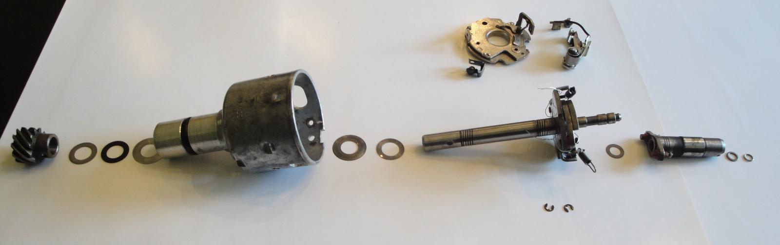 Background: I have known of my bouncing timing mark for sometimes and have learned one of the root causes is ignition distributor shaft axial and/or rotational play. So I called well known distributor rebuilder and told me rebuild time is approximately 5 weeks including shipping both ways. I would have sent it to him if it was Winter season here in Ohio, but to do it now means I won’t be driving my "Ultimate Driving Machine" for 5 weeks. So I decided to take on the task and repair it myself. I knew the distributor shaft has 0.040”axial play. The distributor is original to my 1976 BMW 2002 and part numbers stamped on distributor housing are: 0 213 170 164 // JFU 4 So, proceeded with setting engine at TDC (distributor cam aligned to distributor notch) then removed the distributor. Here are steps for disassembly: Remove contact breaker, capacitor, vacuum regulator and tabs holds distributor cap Next, note indents on distributor body where contact breaker resting on (3 places) From vacuum regulator opening, insert screw driver and pry contact breaker plate up at each indent locations. Other option for plate removal per FAQ member ('76Mintgrun'02) feedback is "rotate the plate counter clockwise to release it from the indents in the housing." Disengage two springs from cam base posts and rotate springs outward. Force cam upward with two screwdriver until retaining clip is out of groove (do not remove felt inside cam hole before cam disengagement) Move the cam upward. There was one trust washer under cam. Note a washer and O-ring clip under felt pad Clamp up helical gear wheel in a vise (use piece of leather to protect gear surface) and drill out pin with 3mm drill. Remove helical gear, trust washer(S) and fiber washer (make note of trust washers stack up) Pull out shaft with counter weights assembly. Again make note of trust washer(s) and fiber washer located underneath shaft counter weight plate. On mine fiber washer was absent under main plate, which explained excess axial play. Clean all the parts with your favorite cleaner. Remember to take a lot of pictures at each dis-assembly stages. Measure trust washer(s) and fiber washer for each group and make notes. Replacement parts: 12111350261, 07119943082, 12111351440, 12118630239 & 12118630245 (not all parts are shown) For assembly I used following instructions: Remember, axial play should be less than 0.005” post assembly completion . Use engine oil and Bosch distributor lube grease for assembly. Soak lubricating felt in engine oil, roll it and slid it inside housing. (on mine felt pad was also missing) Lubricate shaft assembly, counter weights, springs. Slide trust washer(s) and fiber ring over the shaft (rest against bottom of counter weight plate) slide shaft assembly onto the housing and push it down all the way. Slide cam trust washer and then cam over the shaft. Secure the cam with washer and ring. replace felt pad and add couple drops of engine oil on top od felt pad. Slide over fiber washer(1st) and then rust washer(s) to bottom of the shaft. Secure helical gear onto the shaft and push new pin halfway in. Check axial play with shim set. Hold distributor body firm in one hand and pull down on helical gear with other hand. Should not be able to slide in more than 0.005" shim stock over fiber washer. Once clearance is confirmed, press cone grooved pin all the way in. Lubricate contact breaker plates (bottom plate top surface and top plate bottom) with Bosch grease. Secure small "U" clip with ball bearing to contact breaker plate, then set it inside housing. Make sure its mounting holes are lined up with housing clearance holes. Install capacitor, vacuum regulator and tabs holds distributor cap. Set contact breaker to specs. Add cam grease to cam lobe , install distributor accordingly, secure distributor cap. Turn engine on and follow procedure for setting engine timing.12 points
 -
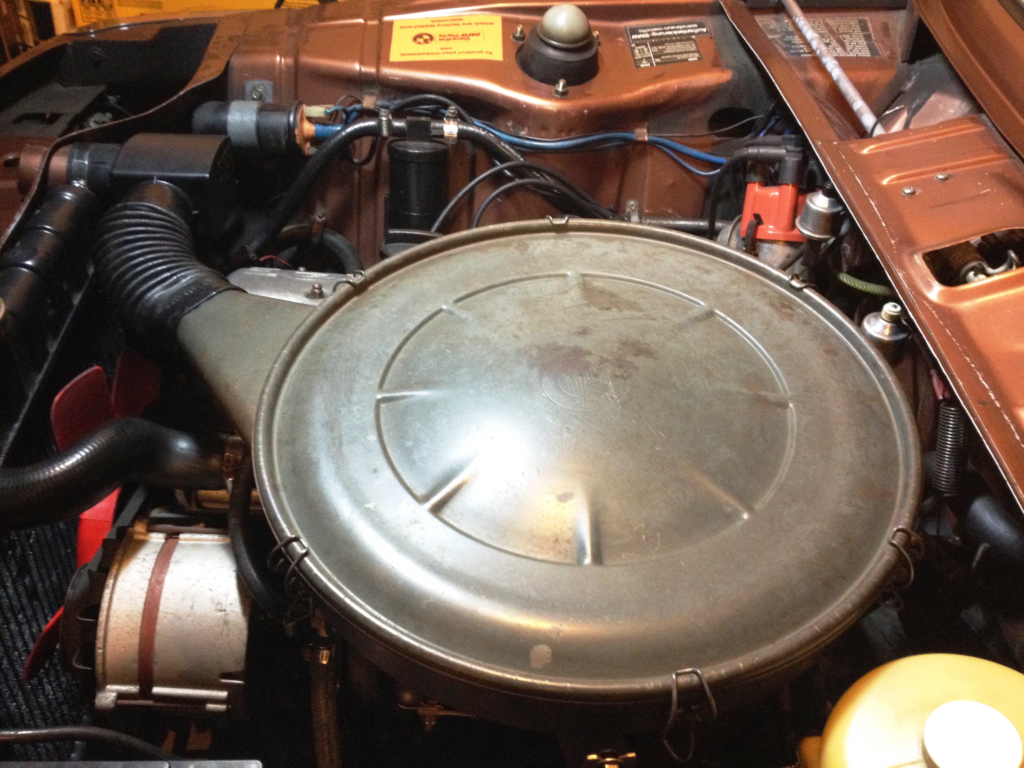 I start by saying always liked "stock look” under the hood and never cared for appearance of Weber 32/36 air filter on my 76 ’02. On the technical side, Weber set up is such that air drawn into intake manifold is always warm/hot (from engine compartment surroundings). So it is opposite of air induction system was originally designed for base model. On original setup for most parts selection of warm and/ or cold air determined by air regulator housing. The original system always let outside ambient temperature air to intake, which it is believed to make engine run smoother and better fuel efficient. Stock air cleaner and weber carburetor Integration has been discussed on this forum previously and there are lots of good information how to do this, but did not find much information on purpose of air regulator box, heat shield over exhaust manifold. So I had to learn about each component as I was acquiring them and at the end found system design quit simple and efficient. So it was learning experience and then I thought why not write article about it. Procedure is written for a 1976 model year car, which I think will be very similar for earlier model years as well, but don’t know that for sure. As I mentioned before I did not have any of original components so I had to place add on this forum under “Part Wanted” section and thanks to members that helped for me to acquire needed parts. After several search and reading up on this topic it appeared that there are at least two methods to accomplish this job if not more; one is to use an adaptor between air filter housing and carburetor; Second option is to not use an adaptor. I don’t know pros and cons of one system to another, but as I recall If none adapter version is decided then a fabricated closed-cell foam gasket should be installed between air cleaner and carburetor. Below pictures (not mine) for none adaptor version for reference. In my case I opted to go with an adaptor version. Here are photos of components that were needed; JAM air cleaner adapter Picture (13/36) Picture (13/39) Fabrication and Installation: Turn-over air filter housing, remove rubber seal and slide the adapter over the air cleaner flange Trace JAM adapter inside and three mounting holes onto air cleaner Remove adapter then remove excess material by various tools (i.e. tinsnip pliers, dremel tool) Drill previously marked holes with ¼” drill bit May want to prime/ paint modified area to prevent future rust Disconnect cable from battery negative post as a precaution Remove Weber air filter assembly including filter base plate, four screws and breather hose Fasten two brackets to intake manifold (picture 13/39, item #1 & 8) Slide down new gasket ontop of carburator Set JAM adapter over carburetor and then place gasket on top the adapter With air cleaner over JAM adapter line up 3 mounting holes. Loosely fasten air cleaner and JAM adapter to carburetor by using M6x45 screws and flat washers supplied in JAM adapter kit. Do not tighten screw yet. Fasten air cleaner to the brackets that were previously fasten to intake manifold. Purpose of these struts are to partially support weight of air cleaner and not all air cleaner weight on carburetor alone Using piece of none braided hose connect cylinder head valve cover vent opening to air cleaner tube opening Remove air regulator box cover screw and withdraw the cover. Oil the valve pivot points and check adjustment. Replace cover and screw then install the box onto snorkel (right rear of the radiator) use rubber boot to connect air cleaner to air regulator box Set new filter in and put the cover on and close clamps Slide heat shield cover over exhaust manifold and fasten it with two M6x16 bolts along with flat and wave washers. May want to apply anti-seized compound to the bolts for ease of removal just in case later on Connect heat shield to air regulator box. Curved tube (picture 13/36, item#6) Slowly try to close hood and absorb to see if hood inside makes contact with top of air cleaner housing. I did not have any interference issue, but if it seems to be the case, you may want to consider followings for remedy; Have machine shop to shorten JAM adapter height by not more than 2mm Thickness of isolation gasket sandwiched between carburetor bottom and intake manifold opening Foam pad inside bonnet Raising bonnet slightly [*]Re-connect cable to battery negative post [*]Have someone to assist with starting the car and ensure hood and air cleaner top not making contact as revving up engine, which in this case engine wants to tilt to right hand side [*]Last but not least need to paint air cleaner so it “looks stock” but have to wait till weather warms up around here. Air Regulator Housing Adjustment With the valve lever in “Summer Position” (vertical) air is drawn only from outside the car Release lever from “summer position” for other seasons. With the valve lever in the horizontal position, air drawn in from front of the car is mixed with air heated by exhaust manifold in specific proportions by the action of bi-metallic element which is dependent upon the current engine and ambient temperatures. 1/27/2014_Rev 111 points
 -
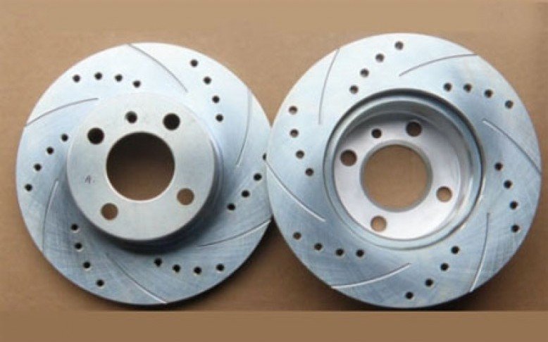 The "big brakes" upgrade is probably the most-frequently asked question when it comes to upgrading an '02 for high-performance driving. In fact "big brakes" is really a misnomer because what we are really after here isn't necessarily a larger diameter brake rotor (although these upgrades below do give you a marginally larger rotor), but in fact rotors that are vented for better cooling. Braking systems are basically heatsinks that suck kinetic energy out of a bunch of flying metal, plastic and glass, and convert it into heat: depositing it in the brake rotor itself. Then the rotor is supposed to shed it into the rushing, cool night air... Vented brakes simply allow this process to take place with more efficiency, in addition to having a higher basic mass which will by itself soak up more heat without failing. Which option you choose to get your vented brakes will depend mostly on where you are starting. For tii owners, the best option is to use the brakes from the e12 early 5-series sedan or e24 6-series coupe. They will fit on the stock tii spindles and require no other modification of the car. For non-tii '02s, really there are two major options. One is to go with all-BMW parts and buy a set of tii front struts. Then use the parts from an e12 sedan or e24 coupe as stated above. The other option is to just use the Girling Vented calipers from a mid-80s Volvo 240, and the rest of the parts from the e21 320i. This will save you some money if you are starting with a "regular" '02, and provide braking on par with the pure-BMW solution above. Please note that Rob Torres, Jr. of 2002 Haus recommends the use of tii struts with their the larger spindles if you are running large-diameter (15"+) wheels, or else you will chew up wheel bearings at a rapid rate! Thanks to Rob for the tip! Other options involve using racing brakes from people like Wildwood and the like. If you are considering operating at this level, the best advice is to find a vendor who will work with you to get the product installed on your car. Some vendors also sell other higher-end braking solutions such as lightweight aluminum calipers, and these kits will come with everything you need to adapt them to your car. Because we are only worried about the DIY-type stuff at this point, here are the details for low-buck, big-bang brake upgrades: Parts Required for tii upgrade: New 1977 e21 Vented rotors Used e21 hubs up through 1979 (junkyard) New or Used e12/e24 up through 1981 calipers (I'd just buy already-rebuilt ones but you could get good used ones or rebuildable ones from a junkyard for less $$) New brake hoses (unless yours are less than five years old, you might as well refresh/upgrade while its apart. Braided stainless ones will give you the best performance.) New wheel bearings Wheel bearing grease New performance brake pads Two pints of new brake fluid (might want to get a pressure bleeder too) If you are upgrading to the "pure-BMW" solution from a standard '02, then you will obviously also need a set of tii struts in addition to the above. Parts Required for non-tii upgrade: New 1977(only) e21 Vented rotors Used 1981-83 e21 Hubs (just get these from a junkyard: dont buy new like I did... ;p) New or Used Girling Vented Calipers for a mid-80s Volvo 240 with VENTED brakes. (There are rumors of ATE Vented calipers also being available but the Girlings are far more available and that is probably for a good reason.) New brake hoses (unless yours are less than five years old, you might as well refresh/upgrade while its apart. Braided stainless ones will give you the best performance.) New wheel bearings Wheel bearing grease New performance brake pads Two pints of new brake fluid (might want to get a pressure bleeder too) Four 1" standard galvanized or stainless steel (why not, right?) washers Be aware that certain 13" wheels will NOT fit over these upgraded calipers. In some circumstances, you can do a little grinding on the outside of the caliper to get them to fit, but you will need to start with a wheel with a good deal of offset amd should be as wide open inside as possible. Project: SAFELY raise the car and put it on jackstands. All the standard disclaimers apply. I don't want to get the FAQ sued because some e46 clownie wandered in here and decided to try this. (;p) Basically, make sure the wheels are chocked behind them, its in gear, the e-brake is on (and working!), and your teeth are gritted. Put a floor jack under the middle of the front subframe with a block of wood between jack and subframe to protect and spread load. Raise the car and then put jackstands under the frame rails that are welded to the front floors. Again use some wood to buffer the stands and spread the load some. Remove the road wheels, then remove the old brake lines and calipers. Theres not much to this, just some angry grunting with the aforementioned gritted teeth and possibly some flagrant cussing. Its also messy work, and you will need to drain the brake fluid, so get a pan or bucket too. Once you have the caliper removed, and the old brake lines (this part can be a nightmare in itself! Get out the vice grips and rhyming dictionary!), remove the cotter pin and big wheel nut, and then the old rotors and hubs (as a unit). Again, this is just dirty, messy but straightforward work. Next is to clean the spindles, and inspect them for wear. IF you have a non-tii car and find that your spindles are shot/worn/etc., THIS might be a good time to think about upgrading to a tii strut-based setup (you didnt already order all the Volvo parts, did you!? - just something to think about before indeed placing that order.) If you have used hubs, you have to remove the old seals and bearings and clean them up. I bought new hubs like an idiot, which I immediately got filthy just by handling them. But, CLEAN them up so that you can put in the new clean bearings and grease. Pack the new bearings with grease. If you've never done this before, the `word "pack" pretty much covers it. Do not OVERpack them because this will interfere with torquing down the main wheel nut. You will want to retighten the main wheel nut in 100 miles anyway, and you can put a wrench on the main wheel nut to give it a good squish, then back off and tighten the nut as described a little more below. Install the new bearings into the hub and install the new seal with a flat piece of wood. As I recall, the seals go in flush with the edge of the hub, but I'm not totally sure about that. Then install the hub onto the spindle. Put the outer bearing, washer, and nut on, then spin the hub and finger tighten the big wheel nut until the hub stops. Then back it off a smidge and then put in the cotter pin. Make sure there is veryvery little to no play in the assembly when you rack it up and down, and that it also spins freely when you spin it with your hand. Put the new rotor on, and then slide the new (rebuilt, etc.) caliper over it with the new brake pads installed. Make sure that the bleeder nipples are facing up, otherwise the system will be impossible to bleed correctly. Next install your new hoses. Some of you Volvo upgraders might want to think about using a tii or for tii people, an e28 master cylinder at this point too. The theory is that a larger set of calipers will require more volume of fluid to move the pistons a given distance. If you have a larger master, this will supply that additional flow. In my case, I used a 528 master cylinder. Im not exactly sure what the deal is with the rear proportioning systems in these various MCs, but since I am going to use rear discs eventually, I havent let it keep me up nights yet. Most people, however, simply choose to use the rear brakes from a 320i. Once you have the rear brakes sorted, then bleed the brakes. Start from the passenger rear, drivers rear, then pass front, then drivers front. Make sure you flush all the old fluid out of the system. Some like to use a different-colored fluid each time they change it so they can tell when the old stuff is gone and the new stuff has taken its place. IF you do this, just make sure the two fluids are compatible chemically or else you can have a bunch of new problems on your hands. Once you've got it all back together, it usually takes about 500 miles for the brakes to fully "seat," so don't go out and "test" them right away (oh, officer! see, i just got this new carburetor and i was just trying to test it..... ;p). Other than that, enjoy the new stopping power!11 points
 -
 Article 1: Original Author: Sam Schultz Valve Adjustment for BMW 1602-2002 M10 Motor The process of adjusting the valves needs to be done at every major service. This service happens every 15,000 miles or so. Failure to properly adjust the valves will cause increased wear and rob your engine of power. Tools: 10-mm wrench 10-mm socket (optional) 0.008" feeler gauge Small allen wrench or piece of bent coathanger Parts tray Parts: Valve cover gasket (11-12-1-734-276) Project: With the engine cool (let it sit overnight), remove the valve cover, 6 castle nuts and 1 bolt. Remove valve cover and, depending on its condition, you should replace the old valve cover gasket as it is NOT reusable. You can start at any cylinder you like, but just keep track of where you start! What you want to do is relieve all tension on the valve you are adjusting by rotating the motor until the valve is fully seated. If you are using the starter to rotate the engine make sure the car is out of gear, e-brake engaged and the positive coil wire is disconnected. If you are rotating the motor by the crank nut remove the spark plugs, and follow the same set up procedures as with a starter switch. My favorite way is to simply roll the car while its in gear. To do this, use a flat spot of hard ground. Disconnect the + coil wire and put the car in 4th gear. (Optionally, you can remove all the spark plugs to make this slightly easier-- you should inspect them now anyway.) Roll the car slowly until the first rocker arm you are doing is on the backside of the cam lobe. Next, tilt the rocker pad forward until it is resting on the camshaft. Back off the lock nut slightly and slide the feeler gauge under the eccentric. Use the small allen key or bent piece of coat hanger to rotate the eccentric until its snug on the .008" feeler gauge. Then tighten the nut. The nut should be tight but don't break or strip it! The gauge should just slide between the eccentric and the top of the valve and should grab slightly as you remove it. Make sure you hold the feeler gauge flat. Be aware that the valve spring itself may compress slightly if you turn the eccentric too much, causing the valves to be too tight when you tighten the eccentric. It is better to have the valve a little loose than tight, but if it is too loose it will cause lower performance, valve clatter and wear. Too tight will also rob power by preventing the valves from closing all the way, and also wear out the cam/rockers/etc. much more quickly, and THEN cause valve clatter... The entire operation can be a little tricky but a novice mechanic can do the job! If you are good you can do an intake and an exhaust valve at the same time (not the same cylinder). Make sure you adjust them all, then replace the valve cover gasket and reinstall the cover. The acorn nuts should only be torqued to 8lb.ft., so don't overtighten them! This will warp the cover and cause leaks, assuming you get away with not breaking the studs themselves. Once you are finished, start the car and listen for any strange noises. Remember vintage BMWs should have some valve noise, not having enough play will cause wear to the cam shaft. The old rule is its better a hair loose than a hair tight. If all is good, then close the hood and take it for a nice run! Article 2: Original Author: pklym Well, I am trying to slowly prepare my '76 02 for a late summer cross country trip. Three years ago I brought the car from Portland Oregon out to Washington DC to attend law school. With six weeks before finals I am finally getting serious about preparing the car the trip back west (will probably leave the car stored somewhere in DC area for the summer before driving it out in August if anyone has suggestions on a safe place to store the car out here). I struggled through the winter months rebuilding my heater box...a few times until it worked right but now that we just had a good rain to wipe the streets clear of snow, I am getting to some more preventative maintenance. After reading everything I could find on adjusting the valves, I decided I would tackle this job. The valves didn't sound particularly off, but my engine does feel a little tired, so I thought I would give it a try. I'm not sure if I have ever had the valve cover off of Bridgette and have no idea when they were last adjusted (I've owned the car for four years, but other than the cross-country trip, and one from DC to Birmingham, AL, I haven't put too many miles on it). I read as much as I could but still did not completely understand the process, mostly I thought "What the hell is an eccentric?" I could not find any pictures of that. Because of my slight confusion, I thought I would try to document my process to make it easier on other first-timers. First things first. Remove the spark plugs, and wires (and I removed the coil wire, I think this is redundant). Then I removed the valve cover breather hose (which is vented straight out the bottom, at some point I will get a catch can and maybe reroute it back into the carb). I undid the VC bolts a little at a time working from inside out, I am not sure if this is necessary but I didn't want to accidentally warp anything. Now I tried to get a lay of the land, I understand the cam no problem, so I looked for the lobes that were pointing straight down (as oriented to the engine, not the ground) to see which valves to mess with first. It is kind of hard to tell when the valve is completely straight down because you can't see down there, but you can tell when the lobe is not touching the rocker anymore. After locating a valve to work on, I slid my .06/.08 go-no-go feeler gauge into the spot just above the valve. I must admit, this took me a bit of time to figure out exactly where it went, but after some trial and error it made sense. I had to bend the gauge pretty severely to work in the area. From there I had to figure out what this eccentric thing is. In the picture below I labeled the nut you have to loosen (it's pretty tight and will move the rocker at first) with a "1" and the eccentric with a "2" For the most part the valves seemed in good adjustment, none of them fit any feeler in higher than .08 so they did not need much adjusting. I felt like it was tough to get the resistance on the feeler exactly where I wanted, but ultimately I just relied on the go-no-go aspect of the feeler. I was confused at how to adjust the eccentric. I knew you could use either a small allen wrench or a coat hanger, but I also read that you turn in the hole of the eccentric. I thought this meant you actually rotated some sort of nut. That's not so, you turn the eccentric along its pivot point. I marked the photo with the way the eccentric moves. I also quickly learned that you have to keep your eccentric tool in the eccentric hole while tightening up the nut or the eccentric would close the valve gap too much. I had to switch to a piece of coat hanger from my original allen wrench tool to get a few of the eccentrics to turn properly. I snugged up the nut, but didn't tighten it too much. I hope that is right (anyone?). After doing the two valves whose cam lobes were pointing down I got in the driver's seat and bumped the starter just a bit and would check what valves were available next, without a helper I had to head in and out of the car a few times to get the cams just right. I did try turning the motor with the fan and the alternator belt, but I could only get it to turn a bit this way, I think I may need to tighten my belt. After checking and adjusting all the valves (a few of them didn't need any adjusting). I put a new valve cover gasket on with a couple dabs of Indian Head Shellac in the corners. I torqued the VC bolts to 96 inch lbs of torque (8 ft lbs), working inside out. This really isn't much. Gapped and inserted new spark plugs, and hooked everything back up. Thankfully the car started back up and seems to run well. Not sure if there was any improvement, but then again they didn't seem much out of whack. I haven't taken it for a spin yet. Next, I will be replacing all my fuel line (except the in-car hose) and sender gasket. I think my carb leaks a bit of fuel onto the intake manifold which ends up making my car hard to start without starter fluid if it has been sitting for more than a few days, unfortunately I don't think I am going to have the time to try and learn how to rebuild a carb before my trip. I would have done the fuel line today but the lady at Autozone (God I hate Autozone but its my only option nearby) threw some 5/16" VAC line in my bag instead of fuel line and I didn't notice until later. I hope these photos help someone, and if anyone who actually knows how to adjust valves and sees anything I did wrong, please point it out!11 points
 -
.jpeg.671912189ba2cf5f1c313cf74feb87e8.jpeg) How to Install a Headliner in a BMW 2002 *All the typical warnings apply. Be careful. Don't cut your fingers off. Read the labels on all tools and chemicals and try not to maim yourself. If your 2002 is in need of a headliner, a professional shop can do the job for $500-1000. I've heard of people bringing their stripped car in with the parts in hand and only paying $100, but I haven't yet found that shop. So, the following is a guide to install a headliner in your 2002 in your garage. It's entirely within the ability of a moderately capable mechanic. What I'm getting at is: If I can do it, so can you. I suggest that you read through this entire guide before getting started on this XX-day job.. Gauge for yourself if you want to take it on. To begin, there is only one variation in the headliner: sunroof or no sunroof. Tools, Materials and Parts Needed Parts: 1X Headliner -Sunroof p/n 51441804085 -No Sunroof p/n 51447480140 10X Headliner Bow Grommets p/n 51447780135 Materials: Contact Cement 2X Small Cheap Paint Brushes 5X Cable Ties 1X Pack of Stick-on Cable Mounting Tabs (next to the cable ties in Home Depot or Lowes) Epoxy or JB Weld 183X 1" Binder Clips - Yes, 183 of them. I suggest buying in bulk from an office supply website A few 1/2" binder clips - Not entirely necessary, but you'll see how and where they can be helpful http://i119.photobucket.com/albums/o143/clayweiland/1967 1600/100_1428.jpg Tools: Wire Cutters A Good Pair of Scissors Latex or Nitrile Gloves Exacto or Small Utility Knife Patience Relative Sobriety Day One: 1. Remove the front and rear windshield - Remove the lockstrips and gently push the windshields out. this might be a good time to consider new seals and lockstrips, if they're old. ***EDIT: Once you remove pull handles, visors, etc. put their mounting screws back in and install the headliner over them. This will make locating them MUCH easier later. 2. Remove the rear side windows. 3. Pull the window and door seals out of their tracks. You can leave the bottom half in. You'll notice that the door seals are glued in below the beltline. As far as I can tell, BMW designed them this way so that you can replace the headliner without having to buy new door seals. 4. Remove the handles, sun visors, dome light and the rearview mirror. Take note of their positions for installation later. 5. Remove the existing headliner. It's held up with glue along the edges and five bows that span the underside of the roof. Be careful not to bend the bows too much. For the non-sunroof models, there is a cardboard piece along the top of the rear window. The headliner attaches to this ans the gap between it and the roof creates a vent for positive air pressure in the cabin to escape; in the sunroof models, it attaches to the window edge. If your cardboard is damaged, find or make a replacement. 6. Install whatever soundproofing you may have had in mind. You don't really need it; BMW didn't use any. But hey, who doesn't like upgrade overkill? Optional but recommended step: Bow Retainers The headliner bows have the ability to swing down and sag the headliner if everything isn't perfectly installed. Mounting tabs to the roof allows the securing of the bows. This makes pulling the headliner tight a lot easier and ensures that the bows won't sag. In short, do it. 7. Peel the sticky backing off five of the plastic mounting tabs. You'll be using a better glue than the weak adhesive backing. 8. Install the grommets and the bows without the headliner. 9. Mix up the epoxy and glue a single mounting tab directly above the middle of each bow. 10. Remove the bows and leave the tabs to cure overnight. Day 2: The Quickening 1. Put on the gloves. Keep changing them if they get dirty. The headliner is off-white cloth, so it will pick up dirt with ease. Unlike the rest of your 2002, the headliner is not easily cleaned. 2. Lay out the headliner and slip the bows into the loops. 3. Measure the bows and the headliner to center them in the loops. Cut the loops to expose the ends of the bows. You'll see later how you'll need to cut the the loops further, but just cut enough to expose the ends for now. 4. Insert the middlemost bow, with the headliner hanging from it, into the grommets and mounting holes. 5. Make a tiny slit with the utility knife just below the mounting tab. 6. Slip a cable tie through the slit and through the mounting tab. Tighten the tie to a loose loop. This is not a mounting point. This tie is meant only to limit the rotation of the bow. 7. Repeat steps 4-6 for the rest of the bows. **You are now going to stretch the headliner into place. DO NOT USE GLUE DURING THIS STEP.** 8. Get out your stash of binder clips and start clipping the headliner WITHOUT GLUE along the top of the rear window cardboard piece. Start at the center and place a clip every six inches or so. Make your way along each side, moving from the center, down each of the C-pillars (the rear roof supports). 9. Next, move to the front. Stretch the headliner forward and clip every six inches or so, starting from the center. Don't pull everything too tight; incremental progression is the key. 10. Clip the door and window edges along each side. 11. Where you are clipping to curves, you'll need to cut slits perpendicular to the mounting edge. Start the cuts one per curve, understanding that minor adjustments will be made. Be careful not to cut too far. Cut short if need be; you can always cut more later. 12. Continue adding more clips; go for one every 3 inches, all the way around, making minor stretching adjustments to take the wrinkles out. 13. When it comes to the places just below where the headliner bows meet the edges, the loops will create undesirable "tents". You need to further cut the loops some more from above the headliner. You can carefully use the knife or carefully pull the headliner to tear the existing cuts. Either way, go incrementally so that you can work out the wrinkles. 14. For the non-sunroof models, at the top corners where the cardboard ends, carefully cut the headliner to transfer from the cardboard to the C-pillar edge. *Note that I glued some green foam to the C-pillar to go under the headliner. This isn't necessary, but I thought it created a nice, smooth detail. 15. Continue clipping and incrementally stretching until the clips are side-by side, leaving no gaps. This is where you may use a few,smaller clips in tight edges. Be sure to have all of the wrinkles worked out before moving forward. TAKE YOUR TIME. You want the headliner to be properly tight by the time you finish. **For sunroof models, you will need to cut out the sunroof section and clip throughout this section as well. I have never done one of these, but I suggest completely stretching and clipping the entire headliner before cutting the sunroof hole. When you have the entire headliner stretched and clipped, cut from the top and start at the corners, creating an “X” in the sunroof section of the headliner. Making this hole will likely create a few wrinkles; restretch and clip from the sunroof section only until everything is as smooth as it was before you cut the “X”. I would guess that this would require an extra 90-100 clips. Now to start the gluing. 1. With the contact cement and a brush ready, remove only five clips at a time. Brush the glue on both side of the edge, as well as the cloth. This is very important; gluing should be on both surfaces before re-clipping. **IMPORTANT!** The glue tends to make the headliner "swell" a little, so be prepared to make small adjustments to remove new wrinkles. Be patient and take your time. 2. Move along the windows, doing only five clips at a time. Do the rear windshield first, then the sides, and finish with the front. TAKE YOUR TIME. *For non-sunroof cars with the cardboard edge, glue the entire excess headliner onto the top of cardboard. You might need to use a screw driver to shove it in there; just make sure that you don't glue the headliner to the roof. *I used a method of flipping one arm of the binder clips up once they had been re-clipped onto a glued section. This was, I could keep track of how far I had gone. 3. Once you finish, marvel at your accomplishment and reward yourself with a beer. A and B Pillar Sections: The factory way to mate the white headliner to the pillar was to glue the headliner in first, then glue the black pillar sections over them. In the case that you a either reusing your black sections, or just don’t want to pull them up, you can carefully tuck and glue the headliner under itself. Be careful and use gloves. I folded the black part over to make a nice edge, then glued and clipped them. The B Pillar transition will be covered by the C-shaped molding, so pull it tight to get rid of the wrinkles, trim it and cover it with the moulding. You might put a little glue in there, just for good measure. Days 3&4: Wait. Resist the urge to move forward until the glue has dried. Really, don't touch it. If you remove the clips too soon, you run the risk of having the edges come undone. If that happens, you'll never get all the wrinkles back out. Be patient and find something else to do. Day 5: Unclipping Time! 1. Now that the glue has dried for a few days, remove a few of the clips and test the dryness of the glue. Due to varying temperatures and humidity levels, the glue may be completely dry or it could still be wet. Be your own judge of just how dry it needs to be. 2. Remove all of the clips. 3. Using a good pair of scissors or a utility/Exacto knife, carefully trim the excess headliner just beyond the glued-down part. 4. Reinstall the rear side windows and their seals. *Install the seal first, then the window.* 5. Push the door seals back into their slots. 6. Reinstall the black C-shaped moulding that presses over the headliner edges. 7. With clean hands or gloves, find the places for the handles, sun visors, dome light and rearview mirror. use the knife to cut a small “X” where each screw will go. For the rearview mirror, cut an “X” across the small, rectangular hole; the mirror pops in with little carefully articulated pressure. I you have a 1966-67 1600 (like mine in the pictures), you’ll have pulled the headliner over the plastic mirror receiver. You’ll need to cut a slit through which the blade of the mirror will slide. For 1966-67 1600’s only The late-1600 and all 2002 mirrors mount with a press-in style mount. Just cut an “X” over the rectangular hole and press the mirror in. 8. You may have some wrinkles left in the headliner from the material being folded up in the packaging. To get rid of this, you can use a hair dryer. I suspect that steam would work even better, but I had no steam-gun, so I used a hair dryer. This takes a little time, so be patient. 9. Reinstall the windshields, being careful not to pull your new headliner out while pulling the seals over the edges.10 points
How to Install a Headliner in a BMW 2002 *All the typical warnings apply. Be careful. Don't cut your fingers off. Read the labels on all tools and chemicals and try not to maim yourself. If your 2002 is in need of a headliner, a professional shop can do the job for $500-1000. I've heard of people bringing their stripped car in with the parts in hand and only paying $100, but I haven't yet found that shop. So, the following is a guide to install a headliner in your 2002 in your garage. It's entirely within the ability of a moderately capable mechanic. What I'm getting at is: If I can do it, so can you. I suggest that you read through this entire guide before getting started on this XX-day job.. Gauge for yourself if you want to take it on. To begin, there is only one variation in the headliner: sunroof or no sunroof. Tools, Materials and Parts Needed Parts: 1X Headliner -Sunroof p/n 51441804085 -No Sunroof p/n 51447480140 10X Headliner Bow Grommets p/n 51447780135 Materials: Contact Cement 2X Small Cheap Paint Brushes 5X Cable Ties 1X Pack of Stick-on Cable Mounting Tabs (next to the cable ties in Home Depot or Lowes) Epoxy or JB Weld 183X 1" Binder Clips - Yes, 183 of them. I suggest buying in bulk from an office supply website A few 1/2" binder clips - Not entirely necessary, but you'll see how and where they can be helpful http://i119.photobucket.com/albums/o143/clayweiland/1967 1600/100_1428.jpg Tools: Wire Cutters A Good Pair of Scissors Latex or Nitrile Gloves Exacto or Small Utility Knife Patience Relative Sobriety Day One: 1. Remove the front and rear windshield - Remove the lockstrips and gently push the windshields out. this might be a good time to consider new seals and lockstrips, if they're old. ***EDIT: Once you remove pull handles, visors, etc. put their mounting screws back in and install the headliner over them. This will make locating them MUCH easier later. 2. Remove the rear side windows. 3. Pull the window and door seals out of their tracks. You can leave the bottom half in. You'll notice that the door seals are glued in below the beltline. As far as I can tell, BMW designed them this way so that you can replace the headliner without having to buy new door seals. 4. Remove the handles, sun visors, dome light and the rearview mirror. Take note of their positions for installation later. 5. Remove the existing headliner. It's held up with glue along the edges and five bows that span the underside of the roof. Be careful not to bend the bows too much. For the non-sunroof models, there is a cardboard piece along the top of the rear window. The headliner attaches to this ans the gap between it and the roof creates a vent for positive air pressure in the cabin to escape; in the sunroof models, it attaches to the window edge. If your cardboard is damaged, find or make a replacement. 6. Install whatever soundproofing you may have had in mind. You don't really need it; BMW didn't use any. But hey, who doesn't like upgrade overkill? Optional but recommended step: Bow Retainers The headliner bows have the ability to swing down and sag the headliner if everything isn't perfectly installed. Mounting tabs to the roof allows the securing of the bows. This makes pulling the headliner tight a lot easier and ensures that the bows won't sag. In short, do it. 7. Peel the sticky backing off five of the plastic mounting tabs. You'll be using a better glue than the weak adhesive backing. 8. Install the grommets and the bows without the headliner. 9. Mix up the epoxy and glue a single mounting tab directly above the middle of each bow. 10. Remove the bows and leave the tabs to cure overnight. Day 2: The Quickening 1. Put on the gloves. Keep changing them if they get dirty. The headliner is off-white cloth, so it will pick up dirt with ease. Unlike the rest of your 2002, the headliner is not easily cleaned. 2. Lay out the headliner and slip the bows into the loops. 3. Measure the bows and the headliner to center them in the loops. Cut the loops to expose the ends of the bows. You'll see later how you'll need to cut the the loops further, but just cut enough to expose the ends for now. 4. Insert the middlemost bow, with the headliner hanging from it, into the grommets and mounting holes. 5. Make a tiny slit with the utility knife just below the mounting tab. 6. Slip a cable tie through the slit and through the mounting tab. Tighten the tie to a loose loop. This is not a mounting point. This tie is meant only to limit the rotation of the bow. 7. Repeat steps 4-6 for the rest of the bows. **You are now going to stretch the headliner into place. DO NOT USE GLUE DURING THIS STEP.** 8. Get out your stash of binder clips and start clipping the headliner WITHOUT GLUE along the top of the rear window cardboard piece. Start at the center and place a clip every six inches or so. Make your way along each side, moving from the center, down each of the C-pillars (the rear roof supports). 9. Next, move to the front. Stretch the headliner forward and clip every six inches or so, starting from the center. Don't pull everything too tight; incremental progression is the key. 10. Clip the door and window edges along each side. 11. Where you are clipping to curves, you'll need to cut slits perpendicular to the mounting edge. Start the cuts one per curve, understanding that minor adjustments will be made. Be careful not to cut too far. Cut short if need be; you can always cut more later. 12. Continue adding more clips; go for one every 3 inches, all the way around, making minor stretching adjustments to take the wrinkles out. 13. When it comes to the places just below where the headliner bows meet the edges, the loops will create undesirable "tents". You need to further cut the loops some more from above the headliner. You can carefully use the knife or carefully pull the headliner to tear the existing cuts. Either way, go incrementally so that you can work out the wrinkles. 14. For the non-sunroof models, at the top corners where the cardboard ends, carefully cut the headliner to transfer from the cardboard to the C-pillar edge. *Note that I glued some green foam to the C-pillar to go under the headliner. This isn't necessary, but I thought it created a nice, smooth detail. 15. Continue clipping and incrementally stretching until the clips are side-by side, leaving no gaps. This is where you may use a few,smaller clips in tight edges. Be sure to have all of the wrinkles worked out before moving forward. TAKE YOUR TIME. You want the headliner to be properly tight by the time you finish. **For sunroof models, you will need to cut out the sunroof section and clip throughout this section as well. I have never done one of these, but I suggest completely stretching and clipping the entire headliner before cutting the sunroof hole. When you have the entire headliner stretched and clipped, cut from the top and start at the corners, creating an “X” in the sunroof section of the headliner. Making this hole will likely create a few wrinkles; restretch and clip from the sunroof section only until everything is as smooth as it was before you cut the “X”. I would guess that this would require an extra 90-100 clips. Now to start the gluing. 1. With the contact cement and a brush ready, remove only five clips at a time. Brush the glue on both side of the edge, as well as the cloth. This is very important; gluing should be on both surfaces before re-clipping. **IMPORTANT!** The glue tends to make the headliner "swell" a little, so be prepared to make small adjustments to remove new wrinkles. Be patient and take your time. 2. Move along the windows, doing only five clips at a time. Do the rear windshield first, then the sides, and finish with the front. TAKE YOUR TIME. *For non-sunroof cars with the cardboard edge, glue the entire excess headliner onto the top of cardboard. You might need to use a screw driver to shove it in there; just make sure that you don't glue the headliner to the roof. *I used a method of flipping one arm of the binder clips up once they had been re-clipped onto a glued section. This was, I could keep track of how far I had gone. 3. Once you finish, marvel at your accomplishment and reward yourself with a beer. A and B Pillar Sections: The factory way to mate the white headliner to the pillar was to glue the headliner in first, then glue the black pillar sections over them. In the case that you a either reusing your black sections, or just don’t want to pull them up, you can carefully tuck and glue the headliner under itself. Be careful and use gloves. I folded the black part over to make a nice edge, then glued and clipped them. The B Pillar transition will be covered by the C-shaped molding, so pull it tight to get rid of the wrinkles, trim it and cover it with the moulding. You might put a little glue in there, just for good measure. Days 3&4: Wait. Resist the urge to move forward until the glue has dried. Really, don't touch it. If you remove the clips too soon, you run the risk of having the edges come undone. If that happens, you'll never get all the wrinkles back out. Be patient and find something else to do. Day 5: Unclipping Time! 1. Now that the glue has dried for a few days, remove a few of the clips and test the dryness of the glue. Due to varying temperatures and humidity levels, the glue may be completely dry or it could still be wet. Be your own judge of just how dry it needs to be. 2. Remove all of the clips. 3. Using a good pair of scissors or a utility/Exacto knife, carefully trim the excess headliner just beyond the glued-down part. 4. Reinstall the rear side windows and their seals. *Install the seal first, then the window.* 5. Push the door seals back into their slots. 6. Reinstall the black C-shaped moulding that presses over the headliner edges. 7. With clean hands or gloves, find the places for the handles, sun visors, dome light and rearview mirror. use the knife to cut a small “X” where each screw will go. For the rearview mirror, cut an “X” across the small, rectangular hole; the mirror pops in with little carefully articulated pressure. I you have a 1966-67 1600 (like mine in the pictures), you’ll have pulled the headliner over the plastic mirror receiver. You’ll need to cut a slit through which the blade of the mirror will slide. For 1966-67 1600’s only The late-1600 and all 2002 mirrors mount with a press-in style mount. Just cut an “X” over the rectangular hole and press the mirror in. 8. You may have some wrinkles left in the headliner from the material being folded up in the packaging. To get rid of this, you can use a hair dryer. I suspect that steam would work even better, but I had no steam-gun, so I used a hair dryer. This takes a little time, so be patient. 9. Reinstall the windshields, being careful not to pull your new headliner out while pulling the seals over the edges.10 points -
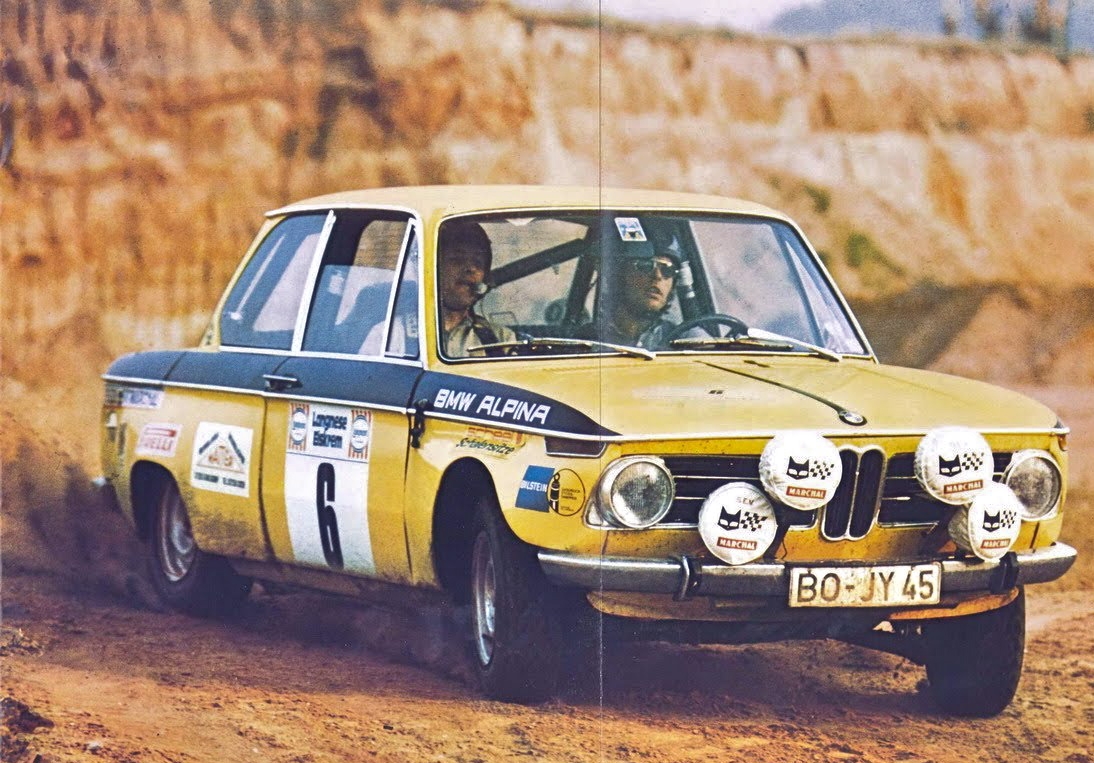 Marchal is a French manufacturer of high quality automobile lights founded in 1923. From its inception Marchal was very active in motorsports, especially in the 1950s through the 1980s. Marchal lights and sponsor decals can be seen on many winners of the 24 Hours of Le Mans and the Rallye Monte Carlo. There are many Marchal lights made during the 60s and 70s which are appropriate for BMW 2002s. The lights are exclusively made in France. Labels inside the housings give the exact week and year of production. Model numbers are always molded into the glass, and usually ink-stamped or labeled inside the lights. Marchal had seen great commercial and racing successes, mostly with Ferrari, in the 50s and 60s with their famous 'FANTASTIC' 660 model as shown above. However, this design, with its distinctive raised center nipple, was looking a little old fashioned by the late 1960s. Light bulb technology also changed dramatically with the introduction of IODE Quartz H1, H2, and H3 bulbs. In 1965 Marchal offered the 'new' H1 bulb in their 'old' Fantastic 660/760 (fog) & 662/762 (long distance) models. Also in '65 the 610 and 612 designs were introduced. Above is a page from a 1965 Marchal catalog introducing the new 610 & 612 models. It also extolls the virtues of the new H1 bulb technology offered in their old 'Fantastic' 660/760 662/762 light range. The bulbs were not called H1 yet, since H2 and H3 bulbs had still to be invented. Strangely, the new 610/612 did not make use of the new IODE H1 bulbs. Even as the 610/612 models were being rolled out, Marchal was already busy working on replacements. A flood of new lights taking advantage of new bulb technology were introduced in the late 1960s. Some lasted only a year or two in production, but other successful designs were manufactured for a decade. Today, all of these lights can continue to provide modern function and period-correct style for your BMW. SMALL LIGHTS - 5.75 inch diameter 610 & 612 (5.75") clear or yellow 1965 - Sticking with the '600' theme Marchal released the the new 610 (fog) and 612 (spot). These were the first polished stainless steel housings offered by Marchal ( as opposed to the previous use of chromed metal). They were very slim. This was achieved by applying the silvered reflector surface directly to the inside of the lamp housing. A stainless band, joined at the bottom by a tiny bolt, held the glass lens, with a more subtle 'nipple', and the stainless body together. This band design was copied by Cibié for use on their super-thin Cibié 45. 610 & 612s in good useable condition are very rare since the reflector coating tended to bubble and separate from the housing. 612 spot light. 710 & 712 (5.75") clear or yellow 1968 - Continuing with the use of polished stainless steel, instead of chromed metal, this was a successful new housing design that stayed in production in some form until the 1980s. The band was gone, replaced by a metal trim ring that pressed into place, and is removed by prying with a flat screwdriver. The flat glass was also new and the 'nipple' was gone, replace in the center by the words 'Starlux'. Most importantly, the light was designed around using the new H1 IODE bulb. 710 is for fog, 712 denotes a spot (long distance) lens. A new logo had been added into the glass as well; a modern and stylized version of the Marchal cat head. However, the twist-off H1 bulb holder was over -engineered. 710 fog and 712 spot light, note 'Starlux' script and the first appearance of the cat head logo. 810 812 & 819 (5.75") clear or yellow 1969/70 - The stainless housing and push-on bezel remained, but the lens and bulb holder were completely new. The nipple was back in the glass, this time topped by a gold anodized aluminum cat logo. This is glued on to the glass, and often falls off due to heat. The biggest improvement was the use of the compact H3 bulb, held in place by a simple and easy to use retaining clip. This model was used in 1975 on the Le Mans class-winning, Marchal-sponsored BMW 2002 of the Heidegger Racing Team. H3 Bulbs are easy to find, inexpensive and as bright as 95 watts. Use a 150mm soft vinyl cover. Hard plastic covers were introduced in 1975. Later production housings are chromed plastic or black plastic. 810 (fog/cornering) 812 (spot or long range) 819 (driving). 810 fog and 812 spot 819 'driving light', a combo of fog and spot light characteristics. This was a new concept for Marchal and referred to rather fancifully as 'Grand Ambiance'. MEDIUM LIGHTS - 7 inch diameter 780 & 782 (7") clear or yellow 1968. A larger version of the 710 & 712 models. Same complicated H1 bulb holder. Yellow glass had the 'cat head' molded into the glass. The clear lenses got an aluminum cat head stuck on. 782 spot light in yellow. 782 spot light in clear with aluminum cat head. 880, 882 & 889 (7") clear or yellow 1970. Again, simply a larger version of 810, 812 or 819 models. Uses the same H3 bulb with a simple and effective clip. Stainless steel housings. Uses 190mm soft covers. Hard covers became an available option in 1975. 880 fog lights in clear glass, paired with hard covers made of slightly pliable hard plastic. 882 spot light in yellow. The black sleeve on the end of the wire covers a female bullet connector for use on your car's wiring. LARGE LIGHTS - 8 inch diameter 1968. To compete with the enormous Cibié Super Oscar (8.5" diameter) Marchal introduced a range of large 8" lights. The first design featured a very deep reflector and housing. H1 bulbs were used. Housings were painted metal. Bezels were chrome. Used a 200mm soft cover. 722/702 (8") clear or yellow long distance SPOT light Note H1 bulb holder. This was soon to be replaced by H2 bulb holders, see below. 722/702 clear SPOT light. Aluminum cat head. Note the new H2 bulb holder which allowed for a shallower reflector and housing. Painted housing, chrome bezel. 720/700 (8") clear or yellow fog light 720/700 FOG light with clear glass and aluminum cat head. Painted housing and chrome bezel. Factory wiring with male spade connector. 720/700 FOG light, yellow glass option. 702 (8") clear or yellow SPOT light. no picture. 709 (8") clear or yellow DRIVING (grand ambiance) light Clear 709 driving lights (grand ambiance). H2 bulbs. Marchal shield in center, no cat. 900, 902, 909 (8") clear or yellow Introduced about 1973. By the 1980s some had black crinkle-painted metal housings and trim rings. Bulbs are the H2 type. Use a soft vinyl or (more common by the late 70s) hard plastic 200mm cover. 900 clear FOG light. Aluminum cat, painted or chrome housing. H2 bulb. 902 clear SPOT light, aluminum cat, painted or chrome housing. H2 bulb. 909 clear driving light. Aluminum cat head, H2 bulbs. Painted or chrome housing. H2 bulb. REAR HIGH INTENSITY FOG LIGHTS - RED Marchal offered a round or rectangular rear fog lights. These high intensity lights were designed for maximum visibility on foggy days to avoid rear collisions. The round light model 642 has a painted metal housing and bezel. The rectangular light model 644 has a grey plastic or chromed plastic housing. RECTANGULAR FOG LIGHTS - 850 fog/cornering. Available with yellow or clear glass. 859 driving. GENERAL MARCHAL NOTES: All the model numbers are molded into the glass lenses and differentiate spot/pencil beam (longue porte), fog/cornering (brouillard) or driving (grande ambiance). Lights ending in '0' are FOG/CORNERING Lights ending in '2' are SPOT/PENCIL BEAM (long distance) Lights ending in '9' are DRIVING (grand ambiance) Fog lenses were not always yellow glass and long range driving lights were not always clear. Until 1993 French law required all headlight or auxiliary lights to be yellow. This meant on French roads either the bulb or the glass had to be yellow. Marchal became part of the Valeo industrial conglomerate, ironically along with main competitor Cibié. Today Valeo supplies lights and electronics to virtually every car maker in the world. The Marchal name was licensed to a Japanese company. Some 1950s designs are reproduced in China. Most of the lights I've detailed above for BMWs are not reproduced, so you will likely come across original items. PHOTO GALLERY 700 series lights. Usually spot lights up top and fog lights at the corners. Note the bumper bracing. 709 driving lights. 8" diameter, H2 bulbs. Big 700 series lights, covered until nightfall on a muddy Rallye Monte Carlo. 819 - Marchal called models ending in 9 'Grand Ambiance' lights ( driving lights) Rallye Monte Carlo The latest 900 series big lights for this entrant in the Tour de France Automobile. This tough rally was a circuit of France on paved and unpaved roads and also race tracks. 700 series spot/pencil beam lamp. Note the 702/722 designation molded into the glass. 882 spot/pencil beam. 7" diameter, H3 bulb. The three sizes of soft covers. These are all the 'two color' design (red and black). The 'one color' design just had the black cat and flag. In the late 1970s plastic housings were introduced. Chromed plastic or black plastic was offered. Same basic housing, trim ring, and H3 bulbs, but different lenses for different purposes. 810 fog/cornering, 812 spot/pencil beam. 880 fog/cornering. 7" diameter, H3 bulb. Rallye of Poland entry showing off for the crowd. The covers in the center are an old design from the 1950s. 1975 Le Mans 24 hour race. Heidegger racing won its class against all odds. Victory for the 2002! Thanks to Marchal lights? Marchal's first 'modern' design of the 1960s. 612 and 610. Short production run, old bulb technology. 882 spot/pencil beam. 7" diameter, H3 bulb. This is the 'one color' soft cover design. The 'two color' option added red SEV Marchal lettering. 810 fog/cornering. 5.5" diameter, H3 bulb. Is Dirand scrubbing off speed or out of control? Note broken headlight. This is a track stage of the 1970 Tour de France Automobile. Big 700 lights braced to the bodywork. Big spot lights protected by 'one color' covers. Smaller fog/cornering lights shielded by 'two color' covers. 24 hour race at Spa Francorchamps in Belgium. What are underneath the headlights, added indicators or signal lights? German entrant in the Rallye Monte Carlo. Spot lights up high - check. Sump guard - check. Sunglasses - check. Helmets...... Snowy conditions on the Rallye Monte Carlo. 710 design (H1 bulb) replaced by 810 (H3 bulb) design. Big 700 series lights. Silver-painted housings, chrome bezels, yellow glass. 810 design replaced the 710. The metal housing and bezel remained the same. This 1969 Rallye Monte Carlo entrant from Switzerland used the older 'Fantastic' models. Note the custom light bar. 662/762 spots up high, 660/760 fogs on the sides, as shown below: Beautiful Marchal 'Fantastics'. Introduced in 1955 but updated in 1965 with new H1 bulb holders in an attempt to keep them competitive. 880 fog cornering lights with clear lenses. 7" diameter, H3 bulbs and hard plastic covers from 1975 on. Hard plastic cover for 810, 812, 819 lights introduced in 1975, with typical crack. 812 light uses blue wire from the factory. 712 light uses a thinner gauge white wire. Rear high intensity fog light. Part # 642-11002. 782 spot/pencil light lens. 7" diameter. H1 bulb. 709 fog/cornering. 8" diameter. Silver painted metal housing. Chrome bezel. H2 bulb. 909 fog/cornering. Same housing and bulb as above but an updated lens with cat logo. When the big 700 series was first introduced the housing was much deeper. This is an 8" diameter 722 spot light with the early deep housing. Also note this early 8" light uses an H1 bulb holder. This was soon replaced by H2 bulb holders and a much shallower housing. 810 fog lights and 702/722 spot lights. The placement of the fog lights up high on the inside is not ideal, but the bumper brackets offer better support for the heavier spot lights. 859 driving light kit from the late '70s or early '80s 859 driving lights FAQ member 'Conserv' took this beautiful photo back in 1977 of his '76 with the latest Marchal rectangular fog lights installed. This page of a Marchal catalog show the light beams of each lens style... Top beam graphic shows Fog light pattern ( lights ending in '0') 610, 710, 810, 880, 850, 700, 900 Middle graphic shows Driving light pattern ( lights ending in '9') 819, 859, 709, 909 Bottom graphic shows Spot light pattern ( lights ending in '2') 612, 712, 812, 882, 702, 722, 902 Early 'Fantastic' 660 fog lights. Design was introduced in 1955 and remained in production with updated 660/760 lens until 1969. Note custom through-the-grille bracket. This glass design is the original 1955 660 lens. It was replaced in the 1960s by a lens marked 660 /760 which had less of a shield motif and more of a 'starburst' design. Norwegian entrant in the Rallye Monte Carlo came equipped with big 700 series lights. FAQ member Jam3422 installed Marchal 712 long distance lights on his exquisite '71 ti. Thanks for looking, please post photos of how you installed Marchals on your BMW..... The 2002ti of co-drivers Prevoteau and Devaux. Event is the 2nd Grand National Tour Auto, France 1971. They finished 2nd in class 18th overall. Drivers Depnic and Belly drove this 2002ti in the 2nd Grand National Tour Auto, France 1971. First in class, 13th overall. Nice combo of 200mm soft and 150mm hard covers. FAQ member 'Pitopop' has super-rare French yellow AMPILUX headlights with matching yellow 709 driving lights. Gorgeous! And the setting's not bad either..... FAQ member '2761876' installed NOS 819 (driving / 'grande ambiance') 5 3/4" diameter lights using mounts that bolt to the bumper bumper brackets. Protection from road rash is courtesy of NOS 6" vinyl padded covers. 1971 24 Hours of Spa Francorchamps, Belgium. ......also the 1971 24 Hours of Spa The three cars above are entries into the Nürburgring 96 Hour Race (!!) on August 17th 1971. Marchal's largest ligh10 points
 -
.jpeg.e8b71753a88f1ffaadc842a8c63b9fb8.jpeg) Replacing all fuses is cheap insurance against electrical failure. Bosch rebuilds are the only one to consider. BMW dealers often have the best prices under their factory rebuilt program. Reversing wires on front turn signals can result in working signals but no dash indicators. Erratic gauges can often be traced to a bad ground, either on the instrument cluster itself, or engine to frame. Too tight belts destroy water pumps; tighten only enough to run the alternator. If you run 32/36 Weber conversion, using the stock air cleaner with an adapter can result in increased drivability. Replacing the front lower door molding plastic clip with the metal retainer used on the other end of the molding helps prevent the door trim from falling off when opening the door. Never install driving lights without using a relay; wiring damage and fires often result. Increased offset wheels are hard on bearings. Service them more often. For better handling cheap 320i rims can be used, 325 alloys are a good bet for a cheap +1 conversion. A 320i radiator is as good or better than the 2002 part it is lighter, and the whole conversion costs $50.00 less than the 2002 radiator alone. If your 2002 runs hot, and the radiator is more than 2 years old, replace it. Never ignore a bad drive shaft coupling (Guibo). To do so can destroy the transmission case. 320i rear drum brakes will bolt onto a 2002 for much improved braking. Braided metal brake lines are more durable and perform better, and cost little more than stock parts. Do not resurface a bad brake disc, replace it. Use of non-original rear brake linings may result in a parking brake which cannot be adjusted. Check exhaust manifold studs regularly; the front stud seals an oil passage and its loss can cause fires and sudden engine failure. When buying a 2002, check for excess engine movement; more than mild vibration may indicate a broken frame mount it can be fixed but it is quite a job. Check the rear sub-frame regularly; they have been known to rust through even on otherwise rust-free cars This can lead to a big, dirty job and parts are getting hard to find. To get drag-race-style acceleration from a 2002, use the gears from a 1976, but be prepared for lots of noise at cruising speeds. BMW O.E. exhaust systems are the longest lasting and most quiet you will find. Do not discard the plastic cover when making door repairs; its job is to keep water out of the car. To restore smooth acceleration action, clean grit from under the pedals, lube the ball mounts and replace the nylon bushing on the accelerator rod. Check shifter mount bolts regularly; loose bolts can cause noise and difficult shifting. Rebuilding a shifter with new springs and bushings job results in much better shifting. Re-using gaskets is false economy. Using headers without a rear mount usually results in premature flange failure. Rebuilding a brake caliper without sleeving is a waste of time; buying new units is a better bet. Try changing brands of oil if your 2002 is using oil. Tailpipe smoke on deceleration usually means valve seal problems. The 320i can be a cheap source of Recaro seats for your 2002. Drain your speedometer cable; it collects water. The factory made the best shop manual; it is bi-lingual and has lots of pictures. To prevent rust, clear grit from under front fenders, especially on top of signal lights and at the trailing edge brace. 2002s run fine on unleaded fuel. 2002 aluminum bumpers are expensive, but may be refinished fairly inexpensively. Use BMW filters. Change brake fluid at least annually. More often if you do driver schools. Use BMW anti-freeze, use distilled water for batteries and cooling systems. BMW no longer makes a 2002 battery that fits, Sears does, and it is cheaper. Use tool handle dip on metal moulding clips to prevent rust. Use compressed air to blow moisture from behind trim. Change rubber fuel lines at the first sign of aging. Use the Bosch blue coil. Consider changing to an electronic ignition. The adapter kit for a late Chrysler New Yorker will allow the mounting of a din style radio in a 2002 console. Use the metal or nylon shift boot retainer; the styrene plastic style breaks. There is a lot of room for stereo gear under the back seat. If a lock must be replaced, a locksmith can re-key it to match the others. Shift levers are available in black or chrome and will interchange. If radio reception is poor, try replacing the antenna. They deteriorate with age. When an electric switch fails, try cleaning the contacts before replacing. Remove bumpers and clean behind them annually. Repco Metal Master brake pads work well. Aluminum bumpers can sometimes be revived with steel wool and a buffer with a wool pad. Grills are easier to clean when off the car. Flush European turn signals are available for a sleeker look. A smaller steering wheel gives a quicker steering feel. On long trips, carry a "road kit" including: Oil sender Fuel line Assorted clamps Fuel filter Thermostat Fuses and bulbs Oil and water Water pump Fuel pump Alternator Starter Belts and hoses Duct tape Wire Gasket in a tube Coat hanger Distributor tune up parts. (It may be overkill, but then I've never been stuck, either.) A fuel filter can be spliced into a broken fuel line to limp home. Even without a road kit, at least carry a fuel filter. Don't slam doors; it is hard on door checks and windows. Broken rivets cause most window mechanism failures; Mercedes sells a repair rivet. Not replacing broken door checks can cause jammed or broken windows. A 530i starter will give you a lot more starting torque. 530i master cylinders give better stopping. Check floor pans carefully; BMW undercoating hides a lot of rust. Tail light gaskets are a frequent cause of trunk leaks. Check the air pressure in your spare. Bellows style shift boots last longer than the fake leather type. Clean out the pedal box, check for rust and debris and enjoy smoother pedal action. If the transmission must be removed, put in a new clutch disc as cheap insurance. A good tight four speed can use ATF for easier shifting. Use genuine BMW Guibo couplings. Shop prices; even dealer prices vary widely. Buy 2002 parts you may need now; many parts go NLA (no longer available) monthly. Use automotive grade hardware; you'll be thankful 2002s have little tire clearance: 185/70 x 13, 205/60x13 and 195/50x15 are about as far as you can go, but there is much variance between individual cars and brands of tires. Rotary compressors give much improved air conditioner performance. New Roundel badges are a cheap way to spruce up the appearance of your 2002. Black spark plug wire can replace discolored "chrome" window trim. The fuel injection system for a 318i can be adapted to a 2002, giving better reliability and economy than carburetors, and less trouble and expense than the tii system. Do not substitute anything else for fuel line. Use Dot 4 brake fluid. Before doing expensive suspension work, consider a full stock rebuild; it is amazing how well a perfect stock 2002 will handle. Adjust your steering box to eliminate "play"; the factory manual shows you how. An upholstery shop can replace the rotted cardboard on otherwise good door panels. Quartz stop light bulbs can prevent rear end collisions. Dim taillights can be caused by corroded reflectors. If used hard, 10,000 miles is not too often to adjust valves. You don't want dual carburetors on your street car, trust me. If your 2002 wears a bra, put soft cloth scraps under the hooks to prevent scratching. For best stereo performance, use large wire; many systems are compromised with small, cheap wire. Short springs seriously compromise the street-ability of a 2002. A 320i differential can be adapted to a 2002 to get access to the much more prevalent limited slip differentials. Not driving a 2002 is the worst thing you can do to it. Remove battery for winter storage. Use WD-40 to displace moisture in hood, door and trunk edge seams. Always wave to other 2002 owners. Author: Scott Chamberlain BMW CCA's Roundel September 1993 Download the PDF.10 points
Replacing all fuses is cheap insurance against electrical failure. Bosch rebuilds are the only one to consider. BMW dealers often have the best prices under their factory rebuilt program. Reversing wires on front turn signals can result in working signals but no dash indicators. Erratic gauges can often be traced to a bad ground, either on the instrument cluster itself, or engine to frame. Too tight belts destroy water pumps; tighten only enough to run the alternator. If you run 32/36 Weber conversion, using the stock air cleaner with an adapter can result in increased drivability. Replacing the front lower door molding plastic clip with the metal retainer used on the other end of the molding helps prevent the door trim from falling off when opening the door. Never install driving lights without using a relay; wiring damage and fires often result. Increased offset wheels are hard on bearings. Service them more often. For better handling cheap 320i rims can be used, 325 alloys are a good bet for a cheap +1 conversion. A 320i radiator is as good or better than the 2002 part it is lighter, and the whole conversion costs $50.00 less than the 2002 radiator alone. If your 2002 runs hot, and the radiator is more than 2 years old, replace it. Never ignore a bad drive shaft coupling (Guibo). To do so can destroy the transmission case. 320i rear drum brakes will bolt onto a 2002 for much improved braking. Braided metal brake lines are more durable and perform better, and cost little more than stock parts. Do not resurface a bad brake disc, replace it. Use of non-original rear brake linings may result in a parking brake which cannot be adjusted. Check exhaust manifold studs regularly; the front stud seals an oil passage and its loss can cause fires and sudden engine failure. When buying a 2002, check for excess engine movement; more than mild vibration may indicate a broken frame mount it can be fixed but it is quite a job. Check the rear sub-frame regularly; they have been known to rust through even on otherwise rust-free cars This can lead to a big, dirty job and parts are getting hard to find. To get drag-race-style acceleration from a 2002, use the gears from a 1976, but be prepared for lots of noise at cruising speeds. BMW O.E. exhaust systems are the longest lasting and most quiet you will find. Do not discard the plastic cover when making door repairs; its job is to keep water out of the car. To restore smooth acceleration action, clean grit from under the pedals, lube the ball mounts and replace the nylon bushing on the accelerator rod. Check shifter mount bolts regularly; loose bolts can cause noise and difficult shifting. Rebuilding a shifter with new springs and bushings job results in much better shifting. Re-using gaskets is false economy. Using headers without a rear mount usually results in premature flange failure. Rebuilding a brake caliper without sleeving is a waste of time; buying new units is a better bet. Try changing brands of oil if your 2002 is using oil. Tailpipe smoke on deceleration usually means valve seal problems. The 320i can be a cheap source of Recaro seats for your 2002. Drain your speedometer cable; it collects water. The factory made the best shop manual; it is bi-lingual and has lots of pictures. To prevent rust, clear grit from under front fenders, especially on top of signal lights and at the trailing edge brace. 2002s run fine on unleaded fuel. 2002 aluminum bumpers are expensive, but may be refinished fairly inexpensively. Use BMW filters. Change brake fluid at least annually. More often if you do driver schools. Use BMW anti-freeze, use distilled water for batteries and cooling systems. BMW no longer makes a 2002 battery that fits, Sears does, and it is cheaper. Use tool handle dip on metal moulding clips to prevent rust. Use compressed air to blow moisture from behind trim. Change rubber fuel lines at the first sign of aging. Use the Bosch blue coil. Consider changing to an electronic ignition. The adapter kit for a late Chrysler New Yorker will allow the mounting of a din style radio in a 2002 console. Use the metal or nylon shift boot retainer; the styrene plastic style breaks. There is a lot of room for stereo gear under the back seat. If a lock must be replaced, a locksmith can re-key it to match the others. Shift levers are available in black or chrome and will interchange. If radio reception is poor, try replacing the antenna. They deteriorate with age. When an electric switch fails, try cleaning the contacts before replacing. Remove bumpers and clean behind them annually. Repco Metal Master brake pads work well. Aluminum bumpers can sometimes be revived with steel wool and a buffer with a wool pad. Grills are easier to clean when off the car. Flush European turn signals are available for a sleeker look. A smaller steering wheel gives a quicker steering feel. On long trips, carry a "road kit" including: Oil sender Fuel line Assorted clamps Fuel filter Thermostat Fuses and bulbs Oil and water Water pump Fuel pump Alternator Starter Belts and hoses Duct tape Wire Gasket in a tube Coat hanger Distributor tune up parts. (It may be overkill, but then I've never been stuck, either.) A fuel filter can be spliced into a broken fuel line to limp home. Even without a road kit, at least carry a fuel filter. Don't slam doors; it is hard on door checks and windows. Broken rivets cause most window mechanism failures; Mercedes sells a repair rivet. Not replacing broken door checks can cause jammed or broken windows. A 530i starter will give you a lot more starting torque. 530i master cylinders give better stopping. Check floor pans carefully; BMW undercoating hides a lot of rust. Tail light gaskets are a frequent cause of trunk leaks. Check the air pressure in your spare. Bellows style shift boots last longer than the fake leather type. Clean out the pedal box, check for rust and debris and enjoy smoother pedal action. If the transmission must be removed, put in a new clutch disc as cheap insurance. A good tight four speed can use ATF for easier shifting. Use genuine BMW Guibo couplings. Shop prices; even dealer prices vary widely. Buy 2002 parts you may need now; many parts go NLA (no longer available) monthly. Use automotive grade hardware; you'll be thankful 2002s have little tire clearance: 185/70 x 13, 205/60x13 and 195/50x15 are about as far as you can go, but there is much variance between individual cars and brands of tires. Rotary compressors give much improved air conditioner performance. New Roundel badges are a cheap way to spruce up the appearance of your 2002. Black spark plug wire can replace discolored "chrome" window trim. The fuel injection system for a 318i can be adapted to a 2002, giving better reliability and economy than carburetors, and less trouble and expense than the tii system. Do not substitute anything else for fuel line. Use Dot 4 brake fluid. Before doing expensive suspension work, consider a full stock rebuild; it is amazing how well a perfect stock 2002 will handle. Adjust your steering box to eliminate "play"; the factory manual shows you how. An upholstery shop can replace the rotted cardboard on otherwise good door panels. Quartz stop light bulbs can prevent rear end collisions. Dim taillights can be caused by corroded reflectors. If used hard, 10,000 miles is not too often to adjust valves. You don't want dual carburetors on your street car, trust me. If your 2002 wears a bra, put soft cloth scraps under the hooks to prevent scratching. For best stereo performance, use large wire; many systems are compromised with small, cheap wire. Short springs seriously compromise the street-ability of a 2002. A 320i differential can be adapted to a 2002 to get access to the much more prevalent limited slip differentials. Not driving a 2002 is the worst thing you can do to it. Remove battery for winter storage. Use WD-40 to displace moisture in hood, door and trunk edge seams. Always wave to other 2002 owners. Author: Scott Chamberlain BMW CCA's Roundel September 1993 Download the PDF.10 points -
 I've used the whole afternoon trying to restore my vent window mechanism. As you all know, the unit is sealed and generally replaced with an alternative working mechanism when it stops working or become harder and harder to turn. I had 6 pairs of these in my spare part stash so decided to pickup the worst and try to refurbish it. This method worked for me and made the mechanism movement feel like new. You're welcome to follow this process if you decide to refurbish your window vent mechanism. Please ensure you clean the unit from any dust, oil or rubbish before this overhaul. Here it goes: 1) So the unit is sealed. The main housing is made of aluminum so you cant just pry it trying to remove the sealed cap, it will brake the housing (trust me, I wasted 2 units already!). Grab a small flat head screwdriver and a small hammer. Gently tap the aluminum edge around the sealed cap to widen the edge. Be gentle or it will crack. 2) Try distributing the pressure evenly. Once the edge is wide enough, use a screwdriver to pup the cap off. (Note where I use the screwdriver, its the strongest point) 3) Once the cap is off, use a small screwdriver or a nail and patiently pick all dried out grease. I used a brake cleaner (spray can) to get rid of old stubborn grease. It wont leave any residue since it will all evaporate almost immediately. You don't have to do this. You could just clean by picking what you see. 4) I used a heavy duty, water resistant, long lasting general purpose grease with extreme temperature rating (non petroleum). The vent mechanism is very similar to steering box mechanism. Apply moderate amount of grease and push it in between the gears then move gears back and forth using the knob. 5) There is a small grease pan under the horizontal gear shaft. Repeat step 4 until you see grease coming out of the top of horizontal gear shaft. This means the bottom grease pan is full. (Try not to over fill). The vertical gear shaft has a small play (moves up and down by 1mm). Using your small flat head screwdriver, try getting some grease under the vertical gear shaft by pushing the other end of the shaft from outside of the housing. This will help smoothing the movement. 6) The vertical gear shaft is supported by a small tension bar from outside where the vent window frame is inserted. Remove the holding screw and tension bar, use small amount of grease on the inside of the tension bar and reinstall (do not over tighten the screw). 7) Now put the cap back on and gently tap the edges inward with a hammer. You're Done! Now, when I finished doing this, I noticed a small amount of grease under the vent mechanism housing where the horizontal shaft is. Looked closely and noticed there is a small hole possibly made for inserting grease occasionally or in major service intervals. But you need to clean out the dead grease before using this grease hole. Most currently available used vent mechanisms have dried out grease and in need of complete clean out anyway and you wont need another overhaul anytime soon! I hope this process is useful to any member. Cheers9 points
 -
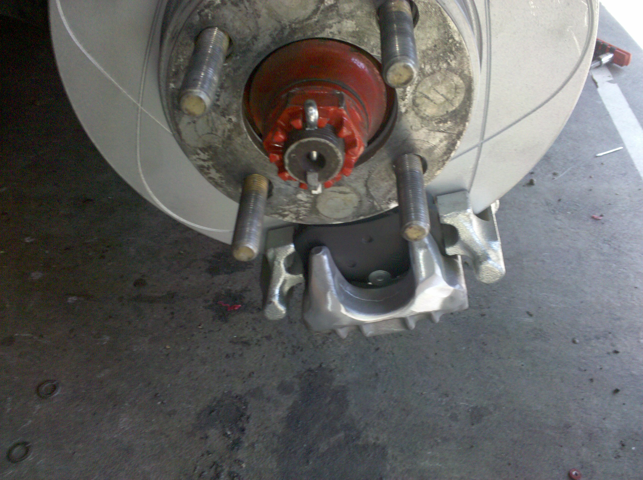 I wanted to change the rear drums on my 2002 to disks. There are no problems with using drums for daily use, but in a race car i wanted to have a bit more maintenance and better consistency day after day. The rules for SCCA FSP class require the car to retain the parking brake. So one of the better ways was to go to the VW Disk conversion. Ireland Engineering sells the full kit that can easily be installed by anyone. What i installed was very similar, but i used an aluminum caliper. Ireland Engineering Kit includes: Custom Steel mounting bracket VW Golf MKII Rear Caliper carrier (1985 to 1989 Golf or Jetta) VW Golf MKII Rear Caliper (1985 to 1989 Golf or Jetta) I used aluminum caliper from MKIV VW. (2000 to 2006 Golf, Beetle, or Jetta) Pros: aluminum, lighter weight, less corrosion, better reliability. Cons: Bleeding can only be done with caliper not mounted to the bracket since the bleeder is at the bottom after the installation. VW Golf MKI Front Rotor (74-84 Rabbit) (239x12mm) You will need to machine the edges of your hub to fit inside the new rotor or IE can do this for you. Several Bolts and Several Spacer Washers To start the installation you will need to remove the Drum, Hub, and backing plate with all the brake parts attached to it. Mount the bracket to the control arm. Try to clean it before mounting. These parts were never designed to be precise but cleaning will make them a bit better for installation something that requires some precision like a caliper. Install the hub and tighten the castle nut properly. Install the rotor over the modified hub and use a couple lug nuts to tighten it to the hub. All this has to be done prior to installation of calipers since and movement afterwards might cause the disk to rub on the caliper. Now it's time to test fit the carrier. Use the washers to get it properly aligned to the rotor. Use lock tight after you have positioning all set Now it is time to fit the caliper and the brake pads. These calipers are equipped with a parking brake mechanism that will require a special tool to push the piston back in place. This caliper can be loaned from your local Auto Parts Store or purchased on Amazon. It will allow you spin the piston as you apply the pressure. At this time you might notice that the caliper protrudes about an inch away from the mounting face of the wheel. If your wheels do not have that much clearance at that spot you will most likely need to use a spacer. Aluminum calipers have cooling fins that make that slightly larger then the cast iron calipers. You might have to shave them to get to fit them inside your wheels Once all is in place, you will need to hook the parking brake over the mechanism of the caliper and do some adjustments on the cable side to get them to be tight You will notice that the bleeder on the caliper is on the side. You will need to undo one of the bolt, swing the caliper and bleed it. You will not be able to use the "pump the pedal" method, but both push and pull vacuum tools work well in this situation. steve k. p.s. if you find any of the information incorrect or you have something to add, feel free to modify the article.9 points
 -
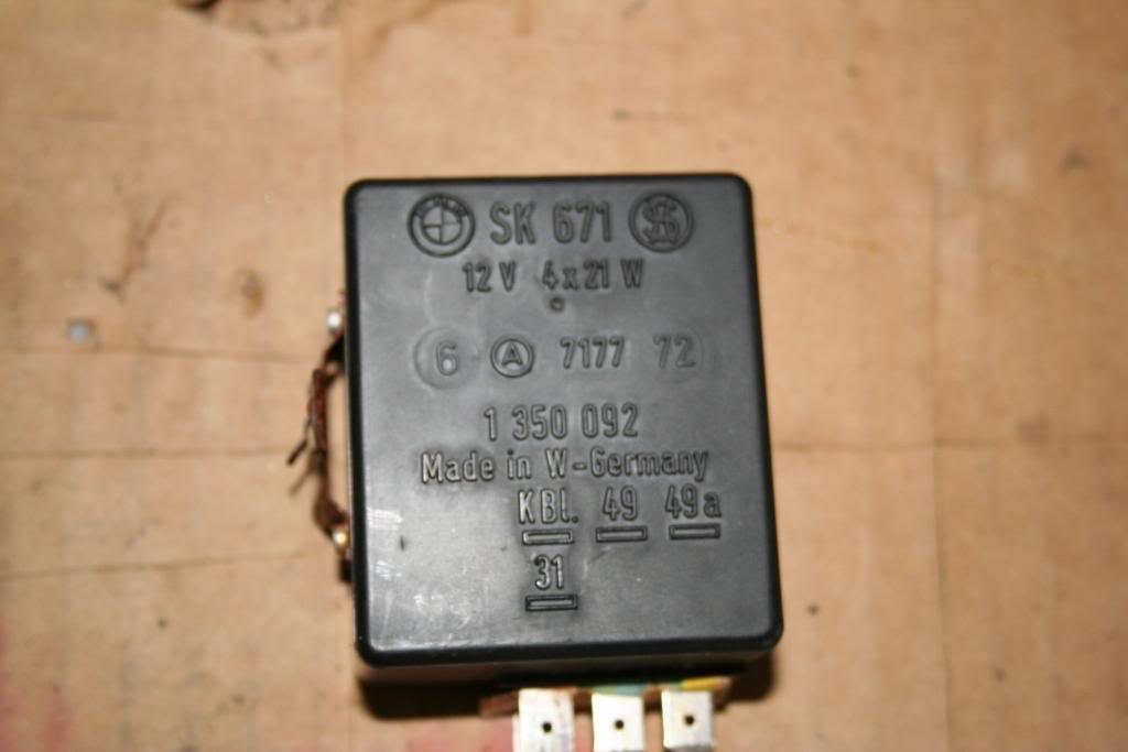 Written by Chris Blumenthal Friday, 30 September 2005 Retrofitting an Electronic Flasher Relay By Chris Blumenthal Introduction Most 02 pilots have experienced turn signal problems. The dreaded indicator light "no-blinkie" and flash-only-once syndromes are among the most common. Another symptom is the fast-flashing indicator. Most of these problems seem to be traceable to excessive resistance in the turn signal/hazard flasher circuit. The '02 turn signal/hazard flasher circuit is notoriously sensitive to bad connections (both - and +) and poor quality bulbs causing too much resistance in the circuit. About 6 months ago, my instrument panel turn signal indicator started working intermittently and finally got to the point where it would only flash once when I first applied the turn signal, even though both front and rear bulbs were flashing as appropriate. I went through my whole system, cleaning up the contacts and grounds, and replacing a couple of brass base bulbs with the supposedly preferable "silver" base bulbs (available from the dealer and aftermarket sources from manufacturers Sylvania/Osram or Philips [others?]). When this didn't fix the problem, I replaced the flasher relay. This fixed the indicator problem, but the flashing (both the indicator and bulbs) was about twice as fast as the original and normal speed... not quite as fast as when there is a burnt-out bulb, but way too fast. Reminded me of the turn indicators you see on the typical death car or '63 VW bus. This just wasn't right for a dignified '02. The only direct replacement relays that I could find were marked "XS," with the X overlaying the S. It is my understanding that these relays are made by Siemens. A quality manufacturer for sure, but all of the OE relays I have seen were made by Hella. I have since tried a few different, used Hella relays lent by friends, but all have exhibited the original indicator blink-only-once problem. My conclusion: something beyond the normal and obvious is screwed up in my flasher circuit, probably in the wiring. I guess I could have lived with the fast flash problem, but it really bothered me. The Solution A few months ago, I happened across Zenon Holtz' web site. Zenon is an '02 brother from the Great White North (well, not so white in BC...) who has a nice BMW related web site, including a discussion (under "tech/troubleshooting turn signal problems") of using a generic, 3-prong turn signal relay in the '02. This got me thinking about using an electronic flasher unit in my '02. I knew from non-'02 related experience that electronic, variable load (resistance) flasher units are available for a pittance (<$5). Besides the low price, the other benefit of using for a generic electronic flasher relay is that external conditions do not determine flashing speed, which is electronically and internally regulated by the relay assembly. In fact, the "variable load" designation means that the flasher will function with different wattage bulbs, variations in circuit resistance, etc. Get a 3 prong flasher unit with terminals marked "X," "P" and "L." There are different spec units available. Littlefuse makes a unit designated "EFL 300" that is appropriate- if you cross reference to that, you will get the right part. The X terminal is the +12V input, the P terminal output drives the flasher indicator in the instrument panel, and the L terminal drives the load (bulbs). In the '02, the typical flasher wiring is comprised of a 4-wire circuit, including the following: brown (ground, of course), black/white (instrument panel flash indicator), green/violet (+12V) and green/yellow (load- bulbs). The brown ground wire is not used with the electronic flasher. The configuration of the male spade connectors on the flasher unit is very similar to a headlight connector. A female headlight connector with pigtails (available at most any auto parts store) works fine as an adaptor between the 3-prong electronic flasher unit and the '02 flasher connector. Note, however, that for a few bucks, many auto parts stores can provide a more precisely fitting plug intended specifically for turn sign flashers. Just solder .25" male spade connectors to the pigtails (use shrinkwrap to cover your solder connections, of course) and plug into the '02 connector. Connect the "L" terminal to the green/yellow wire, "X" to the green/violet wire, and "P" to the black/white wire. Conclusion So, why do this? (1) Endless, cheap source of flasher units; (2) flasher is unaffected by and insensitive to slight variations in resistance in the old '02 wiring; and (3) nicely paced, perfectly timed flashing (again, regardless of slight variations in resistance in the circuit). Although these flasher relays works with variable resistance, this setup will alert you to a burnt-out bulb by increased flashing speed like the original, non-variable load '02 flasher. Note: I am not advocating this as a solution for poorly maintained '02 flasher circuits. Use good bulbs, and keep your grounds, connectors and bulb contacts clean! If you have any questions, feel free to post them to the Message Board!9 points
 -
.jpeg.e8a8c01f6f7c0e79a6dfeb756d739ff3.jpeg) Original Author: Jeff Ireland Differential Types - 2002 and 320i: Early 1600's and 2002's came with a long neck differential. These were phased out in early 1969. They were either 4.11:1 (1600) or 3.64:1 (2002). They are very rugged (heavy) and easy to come by, but not rebuildable due to the lack of available replacement parts. If you want to switch to the later short-neck differential, you must replace the entire subframe and rear suspension. This sounds tough but is actually fairly easy and the parts are readily available. All later 2002's and all 320I's used the short neck differential. These came in several ratios: 3.36:1 -- 2002 Turbo 3.45:1 -- some euro tiis and 6 cyl E21s 3.64:1 -- most 2002s and all 4-speed e21s 3.90:1 -- some 1976 2002s and all 5-speed e21s 4.11:1 -- all 1600s Of all these variations, all of them can be transplanted into a 2002. Variations and how to recognize them: All 2002/1600 diffs have 4 bolts holding the side covers and the output flanges are held in by a large central bolt. CV's are attached the output flanges with 6 - 8mm bolts. Early e21 ('77 and '78) 320i's have four bolts holding the side covers, but the output flanges are held in by a C-clip inside the diff. These diffs usually have 8mm bolts for the CV joints but some use the later 10mm bolts. These early diffs are the same width as the 2002 diff so no spacers are necessary if you are putting one in a 2002. Later e21's have 6 bolts holding the side covers and the output flanges are held by a snap ring just above the splines. You can easily pop out the flanges with a screw driver. These diffs nearly all use the 10mm bolts for the CV joints. These diffs are also narrower than the earlier diffs. If you want to put these into a 2002 you should use spacers to bring them to the proper width. Inner CV joints from a 1979 (and only a 1979) e21 are thicker and can be used instead of spacers if you happen to come across a set. Otherwise, billet aluminum spacers and the proper bolts are advised. Making the Swap: It's common to put e21 diffs into 2002's either to get the 3.90 ratio or the easily available 320is limited slip. The e21 diffs will bolt right onto the subframe and driveshaft. Just remove the 320i rear cover and install your 2002 cover. Please note the possible difference in widths I mentioned above. The final issue is 8mm bolts vs. 10mm bolts. If your new diff takes 10mm bolts for the CV joints, you have a couple of choices. Put 320i CV joints on the inboard end of the 2002 axle (if you can find 1979 ones, so much the better), or option two is to drill and tap six new 8mm bolt holes in the e21 output flanges. Clearly these need to be located with some precision and thus we offer the service at Ireland Engineering.9 points
Original Author: Jeff Ireland Differential Types - 2002 and 320i: Early 1600's and 2002's came with a long neck differential. These were phased out in early 1969. They were either 4.11:1 (1600) or 3.64:1 (2002). They are very rugged (heavy) and easy to come by, but not rebuildable due to the lack of available replacement parts. If you want to switch to the later short-neck differential, you must replace the entire subframe and rear suspension. This sounds tough but is actually fairly easy and the parts are readily available. All later 2002's and all 320I's used the short neck differential. These came in several ratios: 3.36:1 -- 2002 Turbo 3.45:1 -- some euro tiis and 6 cyl E21s 3.64:1 -- most 2002s and all 4-speed e21s 3.90:1 -- some 1976 2002s and all 5-speed e21s 4.11:1 -- all 1600s Of all these variations, all of them can be transplanted into a 2002. Variations and how to recognize them: All 2002/1600 diffs have 4 bolts holding the side covers and the output flanges are held in by a large central bolt. CV's are attached the output flanges with 6 - 8mm bolts. Early e21 ('77 and '78) 320i's have four bolts holding the side covers, but the output flanges are held in by a C-clip inside the diff. These diffs usually have 8mm bolts for the CV joints but some use the later 10mm bolts. These early diffs are the same width as the 2002 diff so no spacers are necessary if you are putting one in a 2002. Later e21's have 6 bolts holding the side covers and the output flanges are held by a snap ring just above the splines. You can easily pop out the flanges with a screw driver. These diffs nearly all use the 10mm bolts for the CV joints. These diffs are also narrower than the earlier diffs. If you want to put these into a 2002 you should use spacers to bring them to the proper width. Inner CV joints from a 1979 (and only a 1979) e21 are thicker and can be used instead of spacers if you happen to come across a set. Otherwise, billet aluminum spacers and the proper bolts are advised. Making the Swap: It's common to put e21 diffs into 2002's either to get the 3.90 ratio or the easily available 320is limited slip. The e21 diffs will bolt right onto the subframe and driveshaft. Just remove the 320i rear cover and install your 2002 cover. Please note the possible difference in widths I mentioned above. The final issue is 8mm bolts vs. 10mm bolts. If your new diff takes 10mm bolts for the CV joints, you have a couple of choices. Put 320i CV joints on the inboard end of the 2002 axle (if you can find 1979 ones, so much the better), or option two is to drill and tap six new 8mm bolt holes in the e21 output flanges. Clearly these need to be located with some precision and thus we offer the service at Ireland Engineering.9 points -
 Contributed by Mars Wednesday, 20 December 2006 By Mars aka Marsman When considering to buy a BMW 2002, there are several things to consider. In the U.S. there were several different models produced. Production for these cars ran between the years 1968 through 1976. This guide will attempt to cover in detail some of the basic differences between each model and their respective year(s) of production. 1. Rust: As with any older car from the 60's or 70's, the most important thing to look for is the condition of the body. You MUST carefully inspect the vehicle for any signs of rust. The most common points of rust on 02's can be found in: Rear shock towers The spare tire well The gas tank area The lower rocker panels on each side of the car The driver and passenger floors (esp. on '76 cars, the passenger floors go bad) The front fenders also tend to rust, especially around the turn signals and where it meets the front nose. Fortunately, they are very easy and relatively inexpensive to replace. Other areas that deserve attention are the bottom of the doors, the rim around the front hood and rear trunk and also the front strut tower assembly. Also look under the car and check the frame rails connecting the front crossmembers to the floors. That having been said, don't let a little rust deter you from buying an 02. Some rust is merely surface rust and other forms of rust can easily be repaired. So long as you are aware of what the car has and needs before you buy it, and as long as the vehicle is priced right accordingly you will be fine. 2. Engine: This applies to both fuel injected models and carb'ed models. Check for any excessive smoking due to oil burning. Note the color of the smoke as well. It can smoke in either blueish, white, or grayish black. The color of the smoke will indicate whether it's simple humidity off of the exhaust manifold, possible blown headgasket, worn valve rings, etc.. Here are some examples of colors and symptoms: Blue smoke on 02's is most often seen on the overrun, meaning if you decelerate from high rpm speeds suddenly a blue puff of smoke would come out of the tail pipe. Blue smoke is the result of oil burning and most often associated with bad valve seals and worn valve guides. This is not major but will require attention down the line. Just be sure to check the oil level regularly. White smoke is most often caused by some sort of humidity coming into the exhaust system. It could be as simple as drops of water hitting the exhaust manifold but usually is caused by coolant leaking out from the head. Somewhere water or moisture is being forced into the combustion chamber and being burned out the exhaust. A cracked head or leaking head gasket could cause these. If possible, momentarily smell the exhaust coming out from the rear tailpipe on a cold start. If it smells kind of "sweet", it could be a sign of a cracked cylinder head or also a potential blown head gasket. Black smoke is caused by raw gasoline burning. An overly rich condition can be the cause by a choke stuck shut, a bad fuel pressure regulator, a plugged up air filter or a bad injector. On carbureted vehicles, the choke and choke linkage could have a buildup of gum and varnish. Typically, if you only get black smoke first thing in the morning, it has to do with the choke or the fuel enrichment portion of your fuel injection system. If you get black smoke all the time, get it fixed NOW. Check for any sludge inside the valve cover or under the oil filler cap. Unusually white/milky substance can be indicative of a blown head gasket. The white milkiness is usually coolant mixed with oil. Ask the owner how long it's been sitting and whether or not it's humid in that area as sometimes lack of running the car and humidity can also cause moisture in the valves producing similar results. Also check for any dark, sludgy or black gummy stuff. Watch out for oil additives as well as some owners will use "stop smoke" additives or other products to masquerade any potential problems. Check for any valvetrain noise(s) or other unusual sounds. Inspect the water pump fan, check for any cracks. The Tii models have a mechanical fuel injection system called the "Kugelfischer" injection system. This system is actually very reliable and dependable so long as it has been kept and tuned properly. If a Tii pump is running well, a good rule of thumb is not to mess with it. Glance the engine compartment overall. Check the coolant cap to see if any discolorations exist, check the motor mounts, and make sure all the components are there such as the reservoir bottle, etc. 3. Differentials The differentials in 2002's are pretty reliable. Simply do a visual check for signs of leaking seals, and listen for noises or whining sounds. Leaking seals or whiney diffs are usually worth repairing since these problems aren't severe. Most often 02 owners will simply replace them with another used unit. 4. Transmission: Manual transmissions are also pretty much bullet proof in 02's. The most common problems with transmissions are bad synchros and faulty or loose output flange or bearing noise. If the noise is very faint, it is considered acceptable, but, excessively loud noise is usually indicative of impending bearing failure. If the trans has a louder noise to it, a rebuild will be necessary or at a minimum replace the layshaft bearings. 5. Model Year Variations/Info: 1968 was the first year for the 2002 model. It's origins came from the former 1600 model after a 2 door coupe concept (1600-2) was conceived. The 2002 model is simply the 1600-2 2 door body designation with a 2.0 litre motor. These are usually identified by missing lower side moldings, simple chrome bumpers, and no reflectors. These have the original round taillights and the front grills are silver & black combination. 1969-1971.5 models are pretty much the same as the '68's, with mild upgrades to the braking systems. Minor interior modifications were made and the long neck rears were replaced with the newer short neck axle. CV Joints were also added, I believe. 1972 introduced the 2002tii in the US, the most desirable of the 02 models. Tii models were fuel injected instead of the traditional carb'ed versions. The Tii stands for Touring Injected International. Prior to this, the Touring International (TI) designation was for the higher performance, dual carb'ed versions of the 02. The Tii's fuel injection was achieved by the "Kugelfischer" mechanical fuel injection system. Tii's had a higher compression than their regular carb'ed counter parts (9.0:1 vs. 8.5:1). Internal engine modifications were made as well. Larger intake valves were added, a completely improved braking system (larger front rotors/calipers/pads, larger rear wheel cylinders and larger master cylinder/brake booster), and a better suspension was added (stiffer control arms and spindles). Wider wheels (5X13 vs 4 1/2X13) were also added. The overall fuel injection changes and higher compression made the Tii good for about an extra 25-30HP over it's predecessor. In 1972, 130bhp was not common and made these cars a blast to drive. Visually, they looked the same as the 71.5's with the exception of the 2002tii badge on the rear. The carb'ed versions stayed the same up until 72.5, where the engine gets a major revision due to new emission laws. This introduced the E12 head. The original heads were stamped with 121 or 121TI. The newer E12 head also benefitted from bigger valves (from 44mm to 46mm). A two barrel Solex carb is used. The EGR, and the air pumps are dropped. Performance was improved as a result. The Tii also gets the new E12 head in mid-'72, combined with aluminum intake runners versus the original black plastic banana tube intake runners found on 121 heads. 1973 yielded no major changes except for the bumpers. The bumpers were extended further out to meet the new U.S. bumper regulations. 1974 introduced some major body changes. The most noticeable are the rear tail lights and bumpers. The "roundtails" are gone and in place are the square tail lights. High impact bumpers were added to meet U.S. federal regulations. The interiors are upgraded with completely new upholstery and simulated wood is added to the gauges. The front grills are now black plastic. The turn signal lever is moved to the left of the steering column, where older models have it on the right hand side. The Tii gets the same body facelift, however, this is the last year for the Tii in the US. 1975 brings no visual changes. The engines are highly modified with emission controls. Thermal reactors were added, EGR's and air pumps, and also the '75's yield lower compression. The '75's are the least desirable as a result. 1976 is the last year of the 2002. No major exterior changes were made, but the emission controls were removed for the 49-state version (non-California) cars. Thermal reactors are no more, which was a welcomed changed. Rear axle ratio is lowered on 49-state cars to improve acceleration up to a higher numerical 3.9:1 vs the original 3.64:1. A new cylinder head (designated the E21 2.0) is used which is the same one the 320i's eventually adopt. The non "49 State" version California cars are identical to '75 models. The '76's are by far the easiest to maintain and own. By 1976 BMW had ironed out all of the problems and as a result the '76's are the most reliable all around models. These are perfect for the first time 02 owner. Turbos & Other Variations Turbos were only produced in 1974, sadly, by BMW. They were introduced before the early crisis in the 70's and high gas sales affected sales. BMW in a panic pulled the plug on the Turbo model. They were never officially imported into the US. Other models not making it overseas were the "Touring" model (hatchback '02s) which were built from '71 to '75. BMW also produced a limited run of targa models referred to as the Baur convertibles. From '72-'75, they existed with targa-tops, a removable metal roof section over the front seats, and a soft fold-down rear window. All of the targa models were 2002's. Convertible 02's were also made in the late 60's using the 1600 model.9 points
 -
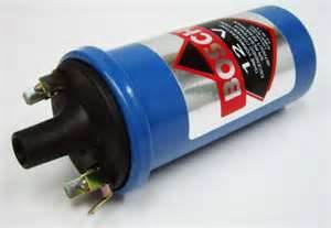 Written by Zenon Friday, 24 March 2006 There seems to be a lot of confusion around coils and resistors so here is my attempt to clarify. compiled from so i am upgrading to pertronix..... and other sources The original stock "black" Bosch coil, with an external resistor, is actually a great setup - superior to a "Blue" coil and equivalent to a "Red". I have seen the specs from Bosch that prove it but cannot find them now. You can trust me, though. ;-) With a Pertronix, you have to run the resistor with either the stock or red coil but must bypass the resistor with a "blue" coil. If you run without a resistor with a coil that requires one, you run the risk of frying the Pertronix because it may not be able to handle the higher current draw. You can also overheat the coil itself. If you use a resistor with a blue coil, you'll get much weaker sparks but your points will last longer. There seems to be a lot of confusion around coils and resistors so here is my attempt to clarify. Why did BMW use an external-ballast-resistor coil, anyway? On all North American '02s (at least from '72-on), BMW fitted the "heavy duty" ignition system that was apparently an option for carby '02s in other markets and standard on tiis and turbo. According to the factory specs and part numbers, the tii and carby external-resistor coils are the exact same part. Essentially, the "external resistor" coil is just a coil that is designed to work properly when supplied with about 9 volts. It is then used with the external ballast resistor so it can safely operate continuously when supplied with the usual 13-14V available when the engine is running. Since a coil's current draw is directly related to the amount of spark energy it might deliver, more current is naturally better except that a coil's current has to be limited to an amount that would not make it overheat in continuous use and/or burn out the points prematurely. But why bother with the external resistor? For normal running, it would be electrically equivalent, cheaper, and more reliable to use a coil designed for the actual system supply voltage and ditch the resistor entirely. The answer is that the whole point of the external resistor setup is to be able to maintain or even boost spark energy during starting, when the system voltage is often pulled way down (under 10V with a marginal battery) by the starter motor and the sometimes very uneven, way rich or lean mixtures are much harder to ignite. By using a coil designed for a lower supply voltage, the designers could then essentially "over-drive" the coil during starting by bypassing the ballast resistor and feeding the coil directly with whatever the battery had to offer. But because the resistor is only bypassed during cranking, the coil would not have much chance to overheat and the points life would not be too adversly affected by a few seconds here and there of switching the much higher current. On earlier '02s with a ceramic-block ballast resistor, there is a relay near the firewall that does the bypassing based on a signal from the circuit that energizes the starter solenoid. On '74 and later, they simplified the design and eliminated the relay, instead supplying battery voltage directly to the coil via a second, smaller spade terminal on the starter solenoid (which is itself a relay anyway). Also on '74 and later, the obvious ceramic resistor was replaced by a sneaky, "special" resistance wire that runs in the harness from somewhere over the engine to the coil's positive terminal - it has clear insualtion and a moulded marker at the coil end with the resistance value on it (by now those are usually just a blob of crispy rubber). All resistors for all years were 1.8ohms, according to the factory manual. Just had a quick look at my manual again and noticed some damn footnotes beside the coil and resistor specs. Seems earlier actually had 0.9ohm resistors but I cannot tell when the cutoff was. If so, that also means the coils were probably different. I still stand by my contention that the stock ignition system with an external resistor coil is the equal of a "red" coil. The only thing is that if you add a red coil or a later "stock" coil to an early car with a 0.9ohm resistor, you will have to replace it with a 1.8ohm or add 0.9ohm. Some final notes: If you run a blue coil and do not bypass the ballast resistor, you will only get full power when starting and much less spark energy when running. A blue coil is actually a downgrade from stock since there is no more "boost" ability during cranking. But, on a well tuned car with a good battery, it may never matter. As mentioned above, if you run a stock or red coil without the resistor, you run the risk of overheating the coil, burning out your pertronix, or going through a lot of points. I have heard some people say red coils work just fine without resistors but I have a hunch they have later cars that have the sneaky resitor wire and they are running them correctly without realizing it. Other aftermarket coils? I dunno - you have to look at each one's specs. You have to be sure the coil you use will not draw too much current for the ignition system you have - points, pertronix, or crane. If you add a resistor, make sure you are not inadvertantly adding it to the stock one or disabling the starting boost feature - it could make all the difference one cold day. regards, Zenon Aaron Heinrich Asks Out of curiosity, what specs on the coil do you look at to determine what is "superior"? If we know what the specs on the stock, blue and red coils are, we should be able to get the pertinent information on aftermarket coils to make an educated decision, presumably. Zenon replies The most useful performance spec would be "total energy" or "energy storage", basically a measurement in Joules or Watt/seconds. The most commonly seen specs are maximum spark voltage and primary resistance. Max spark voltage can be misleading since you can have high voltage with no current and thus no energy behind it (the actual spark voltage is determined mainly by the plug gap, anyway). Primary DC resistance is just an indirect way of getting at the primary current draw but seems to be what is most easily measured and thus is most often stated. The actual current draw in use is dependent on the inductance of the coil, but nobody knows what to do with that. Primary current draw is usually proportional to energy storage so you can maybe use that for comparison, but a bad coil design could draw a lot of current and not make much spark, too. from the archives Bosch lists four types of coils for induction type ignition systems Type E(Black)6V-12V systems for 4 cylinder engines. No resistor needed. Output 13.5 KV. This was the type commonly found on small 4 cylinder engines i.e. Volkswagen, etc. Type K(Blue)6V-12V systems for up to 6 cylinder engines. No resistor needed. Output 17.5KV. This was the type commonly found on 6 cyl VW and as a performance upgrade for 6V systems and lower power 12V systems. Should never be used on BMWs. Type KW(Black) 12V-24V systems for up to 6 cylinder engines. Output 22.5KV. For 12V operation use ballast resistor 0.6-1.0 ohms, for 24V operation use ballast resistor 4.5 ohms. This is the coil that came standard on all BMW engines. As you can see going to a Blue coil would be a significant step backwards. Type KW(Red) 12V systems for up to 8 cylinder engines. Output 26.5KV. Use with 1.4-1.8 ohm ballast resistor. If the ballast resistor is omitted, the points will burn up very quickly. If a transistor trigger is used, then a ballast resistor is not required. When a resistor is required, it should be placed in series with the igniton hot (12V) lead. It should be mounted with a heat sink since it will get quite hot. All induction coils actually contain two wire coils, a primary and a secondary. The primary coil contains a few hundred turns of thick copper wire. Since the wire diameter is large and the wire is short, the ohm reading is very low 0.8-1.4 ohms and the coil will conduct a substantial amount of current to the points. Current flow to the points is a function of voltage, coil wire resistance and points closed dwell time. More than about 4 amps will usually destroy a set of points. The secondary coil contains 15000-30000 turns of very thin copper wire. Since the wire is thin and very long, the resistance is high, usually about 12-18KOhms. Thats a thousand times more than the primary side. While the secondary coil does not flow high current, it does produce a very high stepped-up voltage necessary to jump gaps in the cap and spark plug gap. Hopefully, this will settle the discussion regarding coils. For those who would like to know a great deal more about induction ignition systems, the best text is a training phamplet by Bosch called: "Battery ignition systems" part number VDT-UBE 120/3 En. It covers not only point type ignition but also transistor and CDI type ignitions. After reading the text throughly, you'll agree most information about ignitions is mere marketing hype. Zenon replies The difference between the red and OE coils is probably pretty small in practice since the actual firing voltage when things are working right is under 15Kv, IIRC - I'd put the money elsewhere if my stock coil was otherwise OK. Too bad there is no info on the actual energy storage of the various coils. Even the blue coil might not be as bad as it seems. It looks like the OE coil was essentially the "red" for the last years, at least according to the BMW blue 2002 manual I have. I think there should be a caveat on the statement "[for the red coil] If a transistor trigger is used, then a ballast resistor is not required". I am pretty sure that applies only to the external Bosch ignitor modules (like what came on an e21 320i) but NOT ones like Pertronix. Bosch ignitors are internally current-limited (or just have a beefier switching transistor) where Pertronix ignitors are not able to handle the higher current. At least, the OE and red coils have primary resistances that are lower than Pertronix's minimum spec. so one would be risking it to run an OE or red coil without a resistor. In contrast, I know that some of the Bosch ignitor modules are smarter than that and feature constant, optimized dwell time and will even shut off the coil current after a few seconds if the ignition is on but the engine is not actually running (thus not overheating the coil or themselves). Hey Zenon, Just wanted to personally thank you - without your post I doubt my car would be running today. Andreas9 points
 -
 Spray castle nuts with penetrating oil several times over a course of a few days and let it to break loose surface tension rust and corrosion. Jack up and support vehicle Remove tire Remove cotter pin Replace tire and lower car to ground Apply parking brake and car in Neutral Loosen up castle nut with 36mm socket and long handlebar Jack up and support vehicle again and release parking brake Remove tire, castle nut and drum brake Heat hub for about 15 minutes. Rotate hub as your heating it. Pull off driving flange/hub with extractor Detach output shaft / CV shaft from axle shaft and tie it up Screw on castle nut with notches facing brakes, then use soft hammer to drive axle shaft out ] Outboard Inboard Pry out inboard and outboard sealing rings. From inboard side drive out outboard bearing with soft punch (brass) and hammer. Now shim ring (if any) and spacer sleeve can be removed from outboard side. Now can easily remove inboard ball bearing with punch and hammer. It is imperative that circular shim and spacer sleeve for each wheel kept separate if rear wheels bearings removal done at once. Wipe inside with paper towels and spray inside with brake cleaner. New bearings and seals Next, Pack bearings with grease and grease sealing rings lip Install inboard bearing. I used 1-1/2” dia. PVC coupling and plug to drive bearing in against bearing bore stop. Coat sleeve spacer outside with 35 grams grease and then insert sleeve to the cavity from outboard. Insert shim ring then, install outboard bearing making sure it is seating against shim Install inboard and outboard seals Insert axle shaft from inboard side all the way in Install hub/ driving flange. May need to use hammer on face of hub to seat it in Tighten castle nut with 36mm socket Replace drum brake Install tire and lug nuts Put rear wheels on ground Apply hand brake Secure front and back of rear tire with objects to prevent it from rotational movement Tighten castle nut to specified torque And for last time Jack up and support vehicle Remove tire Install cotter pin and bend tabs Replace output shaft / CV shaft to axle shaft flange Put tire back on and tighten lug nuts Lower the car and torque lug nuts to 65 ft-lb Rev. A: attach CV shaft to axle shaft flange (08/13/2015)8 points
 -
 Parts: Windshield Seals Front - p/n 51317440154 Rear - p/n 51311817764 2 X Lockstrips - p/n 51311803265 2 X Lockstrip Cup p/n 51317440106 Materials: Clear Silicone Caulk Spray Bottle of Soapy Water 25 ft. of 3/16” Cotton Rope Masking Tape Tools: Caulk Gun Small Flathead Screwdriver Lockstrip Tool (I used this one from Aegis Tools.) Apparently, AEGIS Tools no longer sells the roller lockstrip tool. You can get it here now: https://www.hitechglazing.com/product/2781009/40273 *The installation steps are identical for both windshields.* 1. Lay the windshield down and slip the seal over the edges. 2. Wrap the rope twice around the seal, pushing it into the slot. Tape the ends against the inside of the glass. 3. Spray the seal edges to soak the rope with soapy water. 4. Lift the windshield and seal into the opening, being careful not to allow the seal to come out. 5. With one person applying pressure from the outside, pull the rope from the inside, being careful not to pull any of the headliner with it. 6. Once the rope has been entirely pulled and the seal is in, use the caulking gun to run a small bead of clear caulk inside the inside and outside edges of the seal. 7. Once the caulking is in, use the lockstrip tool to install the lockstrip. This is a bit of a challenge and requires a little skill. Go slow and be careful. If you have a small section (1” or less) that pops out of the seal, use the small flathead screwdriver to pop it back in. 8. Trim the lockstrip after installation to fit with as small a gap as possible. 9. Slip the lockstrip cup over one end of the lockstrip and use the screwdrivers to pop it in, using the soapy water to help with lubrication. You’re done! Screw in your visors and handles and pat yourself on the back. This post has been promoted to an article8 points
 -
 Congratulations! You have purchased a unique electronic tool specifically designed for tuning of the BMW Model 2002 - by a 2002 enthusiast! This unit is100% hand built. To use the tool - First make sure the car is in the NEUTRAL position (and/or Park for automatic cars). No key in the ignition, all accessories off (FAN OFF). Locate the diagnostic port under the hood (Driver’s/Left side close to firewall). Simply plug the diagnostic tool into the port; the plug is polarized so you cannot connect it backwards. Once plugged in, you will see some entry text that confirms the tool is properly connected. Youtube presentation: To start the car: turn the red ignition switch up, the red LED must turn on, next press on the start button. Again, make sure the car is in NEAUTRAL. While the car runs, you can navigate thru the display menu with the “select mode” button: 1-Tach mode (default power-up mode) 2-Voltage mode 3-Dwell angle mode (display shows dwell since it cannot show “w”) 4-Oxygen sensor mode (needs to be activated, see below) Note: The start button can be used alone, without the ignition on, for when you would like to make the motor rotate in small increments to adjust the valves, etc... It is preferable to disconnect the coil if you want to do so. Dwell angle is useful principally for original point and condenser system. Pertronix and Hotspark units throw their own dwell values. Pertronix: tested on one car at 65 deg. Hotspark: 20 deg. Point and condenser: (factory suggested) 59 to 65 deg with 0.016” gap User selectable features: -Selectable Tach mode -Selectable 02 sensor mode To change the user selectable feature, you must open the unit and locate jumper J8 “opt” on the PCB, and temporarily short J8 with tweezers while the unit boots-up. Steps: Disconnect the unit from the car (if it was connected already!!) Open the unit (4x Philips screws) Using a pair of tweezers, short both pins of J8 (picture above) Connect the unit to the car while J8 is shorted The unit will display SET UP Remove the short on J8 The unit is now in set-up mode. Lower right dot on the display must be flashing during the process. -To change the 02 sensor mode, press the “select mode” button. The display will show the new setting: Off=02 sensor mode deactivated (default) nb=02 sensor mode activated, narrow band 0-1v lb=02 sensor mode activated, wide band 0-5v -To change tach mode, use again J8 Display will show the new tach setting: 4cyl=4 cylinder mode (default) 6cyl=6 cylinder mode 8cyl=8 cylinder mode Once the change is made, simply disconnect the unit from the car, new setting is automatically saved already. All units are shipped with an extra pin taped inside so you can wire on permanently a 02 sensor on the factory plug on the car. The 02 sensor input is located in the center of the plug on the tool, position #5 on the factory 02 diagram. NOTE: early model 2002’s do not have the diagnostic plug. Disclaimer: This unit is intended to be used on an unmolested, undamaged stock wiring harness. If you have ignition upgrades and extra ignition current consumption, the unit may not work as designed. -turn all accessories off -make sure the car is in neutral Any accidents, mishaps and/or damage involved with this are the user’s responsibility. The supplier of this product accepts absolutely no responsibility for any such occurrences. Technical data: Voltmeter: manually calibrated within 10mv, readout 0-18v 12 bit a/d converter Tachometer: 100% digital 0.5% error 200rpm min 5000 rpm max (4 cyl) Dwell meter: 100% digital ±1 degree accuracy from 200 to 2000 rpm 02 Sensor: Narrow band: 12 bit accuracy a/d converter 0-1v from non-linear 255 points table Wide band: 12 bit accuracy a/d converter, 0-5v linear, 0v=10 afr, 5v=20 afr Reverse polarity protected on all pins 100% designed from scratch for this purpose, by Patrick Allen, it is not an adaptation of another circuit or anything currently found on the market. I own 100% of this design, including the software.8 points
 -
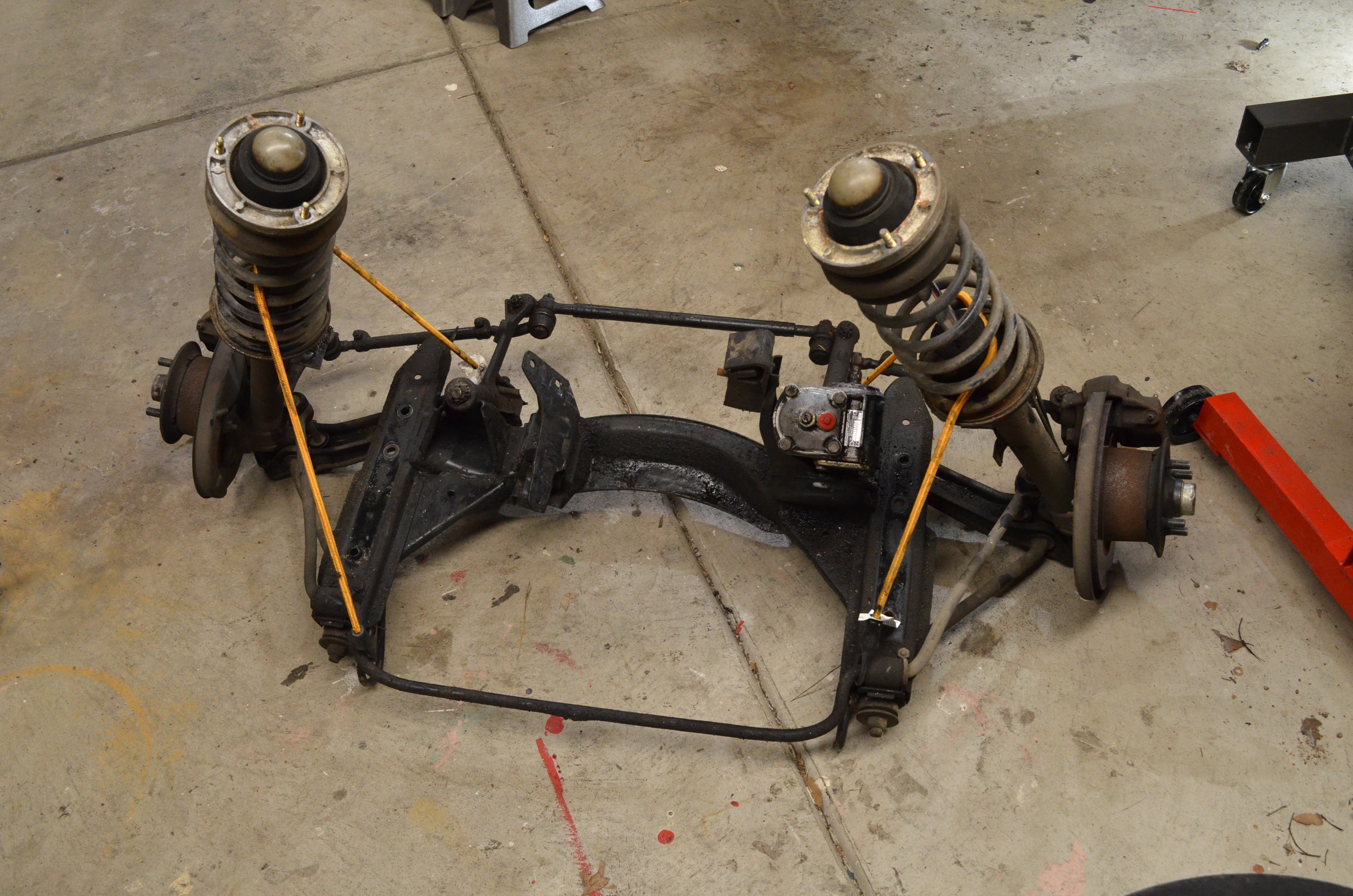 Before I dropped my front subframe, I searched the site for articles that provided the details on how to do this. There were a lot of bullet pointed lists, one or two chronicles and a few older articles that no longer had working images or links. Althought the process is pretty straightforward, it is always helpful to have a little detail, so here is my attempt to provide it. Since I'm working solo on this car, I am breaking things down into one-person jobs. I already have my engine and transmission out, so this guide concentrates solely on dropping the subframe by itself. If you are dropping transmission, engine and subframe as one unit, you will need to disconnect a lot more pieces and the whole package will weigh, what, about 525 lbs? The subframe by itself with the steering box attached weighs about 90-100 lbs. It is not difficult to deal with, but you can't just let it drop either. You will need 11mm, 12mm, 14mm and 17mm wrenches and sockets, a breaker bar, a large flathead screwdriver to use as a wedge (or an actual wedge), a large pair of channel-locks to turn turn the screwdriver if using it as a wedge, some paper towels (for wiping brake fluid), some baggies for your parts and (2) 2-3 foot long bungee cords (for the struts). I also recommend getting a furniture dolly from Harbor Freight so you can set the subframe on it to move it around more easily. Oh, and a box of gloves. Here are the steps involved along with some images. I am assuming the battery is out or disconnected. Jack the car up and put it on jackstands. You can either use the jacking mountpoints or in my case I used the inner body frame members because I already had the car jacked up using those. Remove the wheels. Put the key in the ignition and turn it to acc to release the steering column lock. You will need this to rotate the steering shaft coupling. . With 2 13mm wrenches, loosen up the steering coupling joint and remove the top and bottom clamp bolts. (There is a groove in the splines so you have to remove them completely. Don't forget to bag and tag them.) With a wedge or large screwdriver, loosen up the joint and slide it up onto the steering column shaft. This took a little work but I was able to do it by torqueing a large screwdriver with a pair of channel-locks. The coupling must be up above and completley clear of the steering box. Out-of-focus in progress and in-focus after completion images below. Next, disconnect the brake lines from the front struts using 11mm or 7/16 and 14mm wrenches. I chose to do disconnet the flex lines from the rigid lines on the struts. You will need to drain your brake lines if your brake system is intact. Mine was already partially broken down. Be prepared for brake fluid in any case. Oh, and be sure to save the connector pieces (two little pieces of spring steel) that will end up being loose. Once you get the brake lines disconnected, take the bungee cords, wrap them around the struts and secure them to the suspension on the subframe underneath. This will prevent them from dropping against the fender when they come free of the strut tower later. Next, with a 12mm socket, remove the bolts on top of the strut towers. They will not fall through (yet) and you do not need a spring compressor. Bag the bolts and washers. OK, now we get to the fun part! There are only 6 bolts holding this whole thing on and they are only about 18 inches apart on each side along the bottom of the frame rail. These require a 17mm socket and will probably require the breaker bar to loosen, although once loosened, mine came out very easily. I suggest that you initially remove the front and back bolts and just loosen the middle one on each side. Note that the front bolt is longer. There also isn't a lot of clearance to get a socket onto the rear bolt. With that one bolt still attached on each side, place your floor jack against the crossmember slightly off center a little closer to the steering box. It might not matter, but I did this in an effort to maintain balance. Jack it up snug and orient it so you can hold one of the struts as you are lowering it. Now remove the last two bolts and slowly lower the whole assembly to the ground. Don't forget to bag and tag the bolts. Surprise! It's done! Leave the bungee cords attached so that the assembly is easier to move without risk of a strut falling over. All done! I hope this was helpful. Scott8 points
 -
 There were not many variations of BMW 2002 engines that came off the factory floor in Munich 40 years ago, but over the years, people have made some changes, and some things have remained the same. Here is a collection of the types of engines and inductions you would be able to find in a BMW 2002 at your local car show. This is what things are supposed to look like 1.6L M10 with Solex Single Barrel Water Choke Carburetor on a BMW 1600 2L M10 with Solex Single Barrel Water Choke Carburetor on a BMW 2002 2L M10 with Solex Two Barrel Carburetor 2L M10 with Kugelfischer Mechanical Fuel Injections (Early) 2L M10 with Kugelfischer Mechanical Fuel Injections 2L m10 with Dual Solex Sidedraft Carburetors (2002ti) M10 with a Factory KKK Turbo and Kugelfischer Mechanical Fuel Injection Engine Bay After work done by a Tuner prior to the initial sale M10 With Alpina A4 Intake Engine Bays with Aftermarket Induction Carburetors Weber Downdraft Weber Sidedraft M10 with 36mm Mikuni Motorcycle Carburetors M10 With Lynx Manifold and Single Sidedraft Carburetor Fuel Injection M10 With BMW Electronic Fuel Injection from an e21 320i M10 With BMW Electronic Fuel Injection from a 1979 e21 320i Individual Throttle Body Fuel Injection M10 With BMW Electronic Fuel Injection from an e21 320i and a Turbo Engine Transplants BMW m20 6 Cylinder Engine BMW Euro m20 6 Cylinder Engine BMW s14 4 Cylinder Engine Honda f20c Engine ...And something fun Cardboard Engine I would love to add more to the list, so if you have a similar style photo of something that is not listed, please add it to the comments.8 points
 -
 Original Author: Paul Wegweiser Removing and Rebuilding the Pedal Box Parts Needed: Pedal Box rebuild kit, consisting of: 35 41 1 108 237 Throttle bushings x 2 35 41 1 108 676 Throttle lever spring 35 41 4 440 122 Gas pedal roller 35 31 4 640 116 Clutch pedal to Master bushings x 2 35 21 4 640 103 Clutch pedal pivot bushing 35 21 4 045 707 Brake pedal pivot bushing 35 31 1 104 531 Clutch pedal return spring 35 21 1 102 383 Brake pedal Return spring 35 21 4 440 113 Clutch and brake pedal pads x 2 (THANKS: scottt in New Hampshire for the list of part numbers!) Getting Started: Removing the Pedal Box has to be one of the most-dreaded operations one can perform on an '02. Probably only pulling the heater box is worse in terms of popular perception of the difficulties involved! Total time required for the operation is maybe 3 hours at most - and a truly rewarding repair! The first time I performed this job with the motor OUT of the car - and it was still a royal PITA! I must've wasted 3 hours on a couple circlips and link rod pins. So here's the secret magical method for painlessly removing and installing the dreaded pedal box from an '02. First off: You don't need to disassemble as much as you think you do! THAT is the secret. Pedal box bushing and spring kits are about $35.00 or so - and worth every penny! 1. Peel back carpet so you can easily reach all the pedals, and pedal box bolts. If you've got a later 74-76 car with the one piece carpet - be prepared to go submarining under that nasty funk filled carpet with a flashlight in each nostril and wrenches in your mouth. 2. Loosen the large bolt that holds the clutch pedal to the master cylinder push rod. It's a 19mm / 13mm thing - and it SHOULD have bushings on either side. These generally crack or decompose during removal - glad you got new ones, right? Now pop off the tension spring and circlip holding the vertical rod and clevis block to the brake pedal - push pin off and through toward the left to disconnect. Sometimes this pin is stubborn - but trust me - it'll move out of the way. Don't mess with threading the clevis block unless you want to adjust pedal height. We'll save that for another sermon. Remove all the 13mm bolts that hold the bucket/box to the floor. 3. From the engine bay side - follow the pedal box as it travels up the firewall - and you'll notice it's held in place by a long fat bolt that passes through the brake booster bracket. You do NOT have to remove the bolt to remove the box (that's secret number TWO!) Since the box is slotted at the top - just loosening this nut/bolt to it's last possible thread will allow the pedal box to drop down for removal. If you remove that bolt - you'll spend the rest of the day wrestling with pivot arms, mean, miserable hidden circlips, and scaring away small garden animals as you hurl tools about the yard in primal rage. 4. Now to get under the car. If you were paying attention to the gas pedal as you popped it off, you'll see that there's a steel rod that passes through the side of the pedal box. Now's your chance to start its removal process. Loosen the 10mm nut/bolt that holds the arm lever to the pedal rod, make a note of the spring orientation, and hop back inside the car. Now - from inside the car - wiggle the pedal rod while you pull it to the LEFT - and out of the pedal box. It is NOT possible to remove the box without removing this gas pedal rod first. Trust me - I've tried it six ways from Sunday. 5. Now the hardest part of the job - removing the clutch master cylinder from the box. Reaching those 13mm nuts is a true pain. But if you remove it from the box carefully - you won't have to unhook the supply line or bleed the clutch at the end of this little trip. Plus - a loose supply hose dangling above your head is gauranteed to dribble brake fluid on your noggin! I don't know about you, but I hate brake fluid more than any thing in this world. As if it wasn't bad enough that it stings in cuts, blinds you, makes everything slippery, dissolves latex gloves and stinks; but it'll take the PAINT right off your car too- YAEECHHK!!! Horrible stuff! Treat with care! Now there's only one obstacle holding the pedal box in: the metal brake lines where they are clamped to its side. CAREFULLY pry the tabs back, pull the lines away from the box bracket, and lower the box down. I work from under the car; guiding the clutch and brake pedals down through the hole in the firewall. 6. Once it's out - take a GOOD look at the arrangement of the clutch spring, washers, and bolt holding the pedals on. remove bolt, replace all wearable parts (springs, bushings, circlips) making sure to lubricate everything with a good (I'm a 'Moly guy myself) grease. 7. Reinstall box, clutch master (you'll cuss at the master cyl. It's OK - we all do it!) and finally the gas pedal rod. Having a buddy (thanks Tim!) push the pedal to the floor while you slide on the splined throttle shaft arm at full open throttle (at the carb) will greatly speed up the operation. Best O' luck to ya'! The new feel of the pedals will amaze you! Truly worth all the effort - and only required once every few decades! If you have any questions please post them on the Message Board!8 points
 -
 I am putting in an Esty carpet kit, so i figured i would take some pics along the way. any suggestions to make this process better are appreciated! When you get the box with the kit in the mail, open it up and check out all the cool pieces. Do not lose or misplace one and think Esty forgot to put it in the box. She didn't, you lost it. ? I used Esty's posted instructions as a guide. Things you need: -the carpet -3m super 90 spray adhesive -set of misc clamps from Lowes -razor knife -good pair of scissors -marker assuming you already removed entire interior, put down Rammat and put down a layer of Ensolite.. Start with the back piece that goes under the rear seat. you will have to trim the center tunnel opening to make it 1/4 in larger. once you get that to fit, trim the outside edges as they will need to conform to rocker shape. the top of the piece will be too tall. fold it over the top of the metal wall, mark where the back part of the wall is, and trim off the extra. will be around an inch. now get out the super 90. spray back of carpet and reat seat support (including the top). wait two minutes. CAREFULLY place the carpet in place, starting with the center. work out to the sides. this adhesive is unforgiving. once you touch it together, it is stuck. once the front is stuck, clamp the top vertical part, then fold over the top and clamp it down. in about 10min you can pull the clamps off. next comes the rear side rocker pieces. this did not need much trimming. i just aligned the top unfinished edge with the door edge. needed to cut about one inch slit at front and rear of the seat support to allow carpet to fold down. kit i have put carpet all the way accross the seat mount with the vinyl hanging on the inside. now is a good time to cut the hole for the seat slider lever....and poke holes for the seatbelt bolts! the gluing part of this...i only put glue on the top and first inch or two down the sides. this makes the side panel sort of a flap that allows access to wiring and gas line without ripping up the carpet. next is the front rocker pieces. on these the only trim i did was cut a "V" for stress relief in the top front part about 6in back. if you test fit you will see why. the back of this piece should overlap the rear piece by about 1/2in. i glued this the same way as the rear rocker piece, just the top and about an inch or so down the sides. next comes the kick panels. these in clipped the top back 1/4in of the nice edging off to make it fit easier under the pinch welt. install is pretty easy. jam it as far up as it will go and align the back edge with the door opening edge. on the drivers side don't forget to mark and poke holes for the hood release lever. the upper bolt for this actually needed a little "V" cut in the edging. it helped to clamp the back edge until the glue set. that is as far as i have got so far. more tomorrow when i put the center tunnel piece down.... carpet install....part 2 ok, so the side pieces are in, time to do the mother of all carpet pieces the center tunnel section. first, go buy a second can of super 90 adhesive. the first one is about to run out. next, look at the area around the gas pedal on the floor and the center tunnel. do not layer on the padding or sound deadener in either place, especially if you have or ever want to put a 5 spd in. the extra thickness will interfere with the gas pedal and the room for your shoe between the brake and the tunnel. esty's center piece is pretty close, but you will need to make a bunch of adjustment all around. start at the back. the back of the piece against the rear seat support is the reference. i had to elongate the brake lever opening at the back of the opening. be careful if you widen the opening, it is deceiving, you really don't need much. i also had to make some cuts around the seat support to get it to rap nicely. the gear shift hole was right on. the front and around the edges is where you need to get creative. a number of stress relief slices and "v"'s need to be cut to allow the carpet to lie semi flat. also need to make cut to fit around the gas pedal mounting points. now that you have all the trim and shaping done...here comes the fun part. how to you get this ungainly big piece of carpet covered in glue and place accurately? the trick is not all at once, and don't cover everthing with glue! you really only need glue on the top of the tunnel and slightly down the sides. i laid out the piece upside down and marked in cross-hatch where the glue will be eventually be needed. when putting the piece in, start from the back and apply the glue in sections. don't cover the entire thing with glue! i first did the section from the e-brake back. sorry, no pic's of this part. my patient wife was getting the camera when i stuck it down. next did the rest of the piece. put the tranny in 4th gear to give the hole in the carpet a clear shot on down. adding glue and sticking it down it really helps to have a second set of hands at this point to carefully place the carpet and hold it down until the glue sets. end part two. ------------------------------- carpet install - part 3 at this point you have two options. you can flip up the sides and spray glue under there to stick them down, or you can leave it as is. i think i will leave the center section as is. i made enough stress relief cuts that it actually hangs nicely. once the center console is in, it will be fine. leaving the flaps unglued also makes it easier to run wires underneath. the floor mats really don't need to be glued at all, the set nicely in place and don't move around. here are some pics with the floor mats in place. note, getting the drivers side around the pedals is not that bad. clutch on first, then brake, then push it way down and twist it 45deg to the left. gas pedal stub should slide on at this point. once the mat is down, use a razor knife to make two front to back slices over the gas pedal studs to let them poke through the carpet. there is one place where i will ask Esty for her opinion on fit. maybe it is my car. the pass side front floor mat looks like it could be an inch thinner on the tunnel side with maybe a little more curve. as you can see from the pics, it bunches up just a little. since is is nicely trimmed in black,i did not want to make a stress relief cut in it. there are still some details i need to finish, like poking holes for the seat belt bolts and the seat mount bolts, but the install is 95% done. i will refinish the seat mounts before getting to the little details. ------------------------ with the exception of the pinch welt, I finished the carpet install. wow, what a difference!! Esty's carpet kit came out great. overall, very happy with the Esty Carpet Kit! It was not that difficult to install, and her sense of humor in her blog instructions was great! highly recommended if your 02 needs new rugs... ?7 points
 -
 Hello, my name is Fernando im from Guayaquil, Ecuador. I am a proud owner of a 1974 round taillight bmw 2002, im in the process of installing an f22c engine and the power goal is 750hp, i know it sounds crazy but we have cover every single aspect of the car, brakes, suspension, subframe, etc. Enjoy the pictures and feel free to ask any question. Engine F22c, fully built by Inline pro Precision 6466 Fullblown intake manifold Catuned Monster Subframe (E30 medium case 3.90 with special clutches to handle 850hp) Catuned Coilovers Custom engine mounts Chase Bays harness Aem EMS V2 Clutch master twin disc 15gal Fuel cell Rear mounted mishimoto radiator Wilwood big brake kit front and rear 15" and too many other parts to be listed.7 points
 -
 Using this Google spreadsheet developed by Grice Mulligan, AKA williamggruff, users and abusers alike can investigate the outcomes of matching various BMW transmissions and differentials, and calculate a variety of RPM and speed values that result. Inputs are simple: Tire circumference and Redline RPM. Tire circumference can be estimated using the link provided. Redline RPM can be a target RPM, such as a preferred RPM at a cruising speed. BMW transmission gear ratios and differential final gear ratios.xls7 points
 -
 So it's time for an update that I've been working on for the past month or so, it's a long one so be prepared! I recently wrapped up this big project and wanted to share it with everyone. Last year I designed and built a few custom metal/wood roof racks that were compatible on the BMW E10 (1600/2002) and E30 chassis. In total I built three rack systems but eventually decided to pursue other ventures. I was recently approached by Andrew Adams at Ireland Engineering who was interested in having a custom rack built for his 2002 project (which is an awesome build by the way, check it out here: http://www.r3vlimited.com/board/showthread.php?t=211891). After a few messages back and forth I was happy to take the project on and decided it would be a good opportunity to thoroughly document every step of the way to shed some light on how I build things the way I do. Andrew was very lenient and gave me full creative freedom on the design with one request being that it could mount three sets of snow ski's in some way. With this in mind I went to the drawing board, came up with a few renderings and got to work. I used the same mounting solution that I designed last year for this build, but everything else is custom and one of a kind. This project was a lot of fun and VERY time consuming. I'm really looking forward to seeing this rack on the completed 2002 project in person in August! A big Thank You to Andrew for being so easy going and open to my ideas. A quick note I'd like to add: while I was happy to take this project on, I am currently not taking on any other custom roof rack projects at this time. To show where this build is headed, here are a few renderings I came up with which gave me the general design that I wanted (feel free to make fun of my ski's I drew haha): So now, let's get started! The very first step is to bend these tabs into the shape pictured below. They start off as flat CNC plasma cut pieces that get bent in my press brake, I carefully measure them out so they are all the same: This random little tool I made serves two purposes and it helps me make sure every mount and bracket are exactly the same: For one, it helps me set the "sleeve" coupler on the main mount. I line the bottoms up, clamp it onto the mount body and then set a 5/16 coupling nut in the right place: From there I clamp the 5/16 coupling nut to the mount body, it is now ready to weld into place: Welded up on all four mount bodies: Then come the CNC plasma cut pieces that make up the sides of the mounts: I create a very simple jig that helps me set them in the correct spot for welding: Once both sides are welded on, the mounts look like this: Now that the mounting feet are done, it's time to move onto the mounting tabs. They actually secure the mount to the roof of the BMW by clamping around the rain gutter. They start off as flat CNC plasma cut pieces: I custom built a simple brake out of some scrap 3" angle iron to create the profile of these mounting tabs. Here's how it sits before and after the bend: 4 mounting tabs bent up: Here's where that random little tool from earlier comes back into play, it helps me set the mounting tab coupling nut. I clamp it in a specific spot so it acts as a guide for the coupling nut to sit perfectly centered on the tab, which then gets welded up: After some clean up the mounts and tabs are complete and ready for powder coat. I'll show how they actually work at a later time when they are mounted on a car: Now that the mounts are finished up it's time to actually build the rack itself, so I started off by cutting up these pieces. This is 1"x0.5" rectangle tubing and these will act as the main basket "runner bars". I then welded everything up and ground all the welds smooth to achieve a seamless look: Cut a few pieces of 1"x0.25" flat strap: These will act as supports for the runner bars. Welded them in and ground everything smooth: Next up, I built this frame out of 0.5" square tubing: This connects the runner bars and creates a basket: Added top bars and ground all the welds smooth. The basket is now complete: Now it's time to create the cross bars which consist of two pieces of 1"x1.5" rectangle tubing, each having 8 precisely measured and drilled holes in them: I welded these bars to the bottom of the basket: Flipped right side up. Here you can start to see why the holes are drilled the way they are: It's time to build the ski mounts. I cut up two pieces of 1.5"x.025" flat strap: I put a rounded 90 degree bend in them with my compact bender: The ski mounts will be integrated into this part of the roof rack: Clamped them into place, ready to weld: Welded up: I needed to figure out a way to strap the ski's down to the bars, so I tossed some ideas around and eventually came up with these little hoops that I bent on the compact bender: Which eventually led to this: At this point, the roof rack is finally complete and ready for powder coat! With the metal working portion of this build done, it was time to send everything off to the powder coater for a shiny metallic silver finish and set my focus on the wood working segment, which requires a whole different set of tools and consumables. I chose redwood because it is lightweight and handles the elements pretty well. After figuring out what I needed, I went out and bought two long boards of it: I needed 4 wooden slats at a specific length, width and thickness, so I started to mill them down. The first step was to cut each board in half so I had 4 separate pieces, and then I ran them through the planer so that everything would be 0.5" thick: Once the thickness was spot on, I ran each board through the jointer to create a perfectly straight edge: The straight edge allowed me to achieve an accurate cut on the table saw, bringing every board to the desired width: Alas, I have 4 properly sized boards: I wanted to put my new router to use, so I busted it out: I then proceeded to give all the top edges of the wooden slats a 45 degree bevel to add some detail: Carefully measured, drilled and countersunk the holes to mount the wood slats to the roof rack: Gave everything a final sand and applied a coat of stain to the redwood to get the color I was after: Protection. Now that I had the color I wanted, I needed to protect it while not compromising it's appearance. I purchased an oil-based exterior grade polyurethane and created a "wipe-on" application by diluting it 50/50 with mineral spirits: Applying this is a VERY tedious process. Since it's goes on thin, you have to put on extra coats. In total I laid on about 10 coats over the coarse of the next 2 weeks. This is definitely not the most efficient way to do this, but I wanted a hand rubbed finish. If I were to produce these on a more consistent basis I would figure out a better solution to this step: This concludes the wood working portion of this build! The rack came back from powder coat and looked great, I personally love this metallic silver finish. Since a wood slat sits over the driver's side mounting feet, I have to mount them from the underside of the rack so that all of the wood looks cohesive on top. This is why I have these two larger holes drilled in the cross bars pictured below: These are rivet nuts, and they are the solution to my problem: To install a rivet nut, I thread it onto the tool and place it into the hole as shown: I then pull the handles together, which crushes the rivet and forces it to clamp itself to the wall of the steel tubing very tightly, leaving a threaded insert: This allows me to bolt the mount in from the underside only, so there are no signs of a bolt on top. You can also see here how the mount is designed with a slot to adjust the width of the rack for different sized roofs: At last, the time has come to install everything and see it all together for the first time! Very happy with how it turned out and I cannot wait to see it on Andrew's awesome 2002! Thanks for looking and please let me know what you think!7 points
 -
 And we are ....Alive! Welcome to new and improved FAQ. A lot of things are new and a lot has stayed the same. Almost all posts and topics have been preserved. Yes we lost some due to database corruption on the old site. Look around, use what you want! We now have Gallery, Video Sharing, Personal Messages, Blogs, very good Classified Section, Chat, Garage, Groups for all the local chapters, Calendar that is better visible and integrated with Event's forum, members Map, Feedback and Status Updates. Enjoy it all and let me know if you find problems. There probably will be a few. steve k.7 points
 -
 Love me some '02.. and the places mine has taken us. As well as the friends I have made, while.. iphonein'.. Or laughin' at em... Or takin' delivery of em.. Or wrenchin' on em... sayin' goodnight to em.. Or bein' 3 in em.. Or just steppin' back to look at em.. Or apexin' turns in em.. Or upgradin' em.. Or rockin' out with em.. Or trekkin' in em... Or Photoshopin' em... Or going' to grandma's in em.. Or takin' the highway that's the best, in em.. Or rallyin' friends for em.. Or puttin' em up in em.. Or waitin' in line in em.. Or modin' em... Or servin' refreshments from em.. Or missin' the kickoff on Sunday in em.. Or Facebookin' em.. Or learnin' the hard way in em.. Or haulin' babies in em.. Or watchin' the scenery in em.. Or youtubin' em... Or strippin' em.. Or thrillin' the ladies in em.. Or .. dang, he's cute.. Or sharin' em.. Or comparin' em.. Or reminiscin' about em.. Or hangin' out with em.. Or grabbin' a cone in em.. Or representin' em... Or bein' silly with em.. Or acceptin' help with em... Or cheesin' out about em.. Or savin' em.. Or organizin' em... Or smilin' at her in em.. Or racin' em... Or findin' em... Or learnin' in em Or photographin' em.. Or wellin' up over em.. Or revellin' in em.. Or drivin' em... Or drinkin' with friends after drivin' em... Or lookin' over in em... Or random sightin's... Or gettin' dirty with em.. Or puttin' little things on em.. Or bein' seen in em... Or gettin' up under em.. Or introducin' people to em.. Or takin' "mistery rides" in 'em.. Or seeing her grow up, get her own and leave in...one.. It all just adds up, to just lovin' em..6 points
 -
 Production numbers of different variations of 2002s and other Neue Klasse cars. If you have updates to these numbers, please add them to the article.6 points
 -
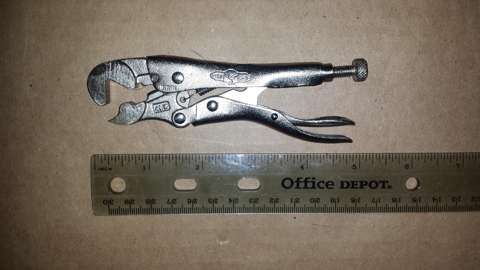 I knew I needed new brake hoses when I tried to bleed my brakes and could not get any fluid to come out of the wheel cylinders because of the 40 year old swollen rubber lines. I knew my front hoses were replaced about 20 years ago because of the 9/94 date on them so I decided to replaced them for good measure. I started with the front drivers side. After soaking the fittings with PB Blaster for a couple of weeks, I tried to remove the front hoses. The nuts on the line would not turn. I tried cleaning the outside of the lines, I tried heat, nothing seemed to work. I ended up rounding over the nuts with my flare nut wrench and had to cut them off with a Dremel, ruining the brake lines. Not fun but I was able to put new cunifer hard lines and braided hoses on the drivers side. On to the passengers side. I really didn't want to have to cut the nuts off and replace the line that ran from the hose, along the firewall to the MC with the engine in the car. There had to be a better way. I remembered an article I had read about penetrating oil comparisons. PB Blaster, Liquid Wrench and Kroil were all good but a 50/50 mixture of ATF and acetone was much better. So I mixed some up and put that on everyday for about a week with a syringe and tube. Trying to find a better way, I read online that the nut on the hard line is locking the hard line in place and the trick is to hold the nut still and turn the hose instead. I had to find a way to hold the nut without destroying it. Then I found a pair of small 4LW vise-grips specifically made to hold hex nuts. One jaw has a V that fits on two flats of the nut and the other jaw holds the opposing third flat. I was able to get a very good grip on the nut. I found the vise-grip on Amazon and they are made for hex nuts 1/4 to 9/16. http://www.amazon.com/Vise-Grip-Adjustable-Locking-Wrench-Cutters/dp/B0076ITU64/ref=sr_1_1?ie=UTF8&qid=1425148634&sr=8-1&keywords=VISE-GRIP+4lw#productDetails Holding the vice-grip stationary, I had to exert extreme force to the 14mm wrench on the hose. With a loud snap. it broke loose with out damaging the line, nut or hose. I was then able to do the same for the other three nuts and remove the hoses. New stainless steel braided hoses The bleed nipple on top of the right caliper was also frozen and had been rounded in an effort to open it. A six point socket was not going to work. I needed to use a different vice-grip with teeth to lock down on the bleeder. I did not want to crush the bleeder and break it off so I put a 1/8" drill bit in the bleeder for strength. With the bit out and my eye protection on and a fire extinguisher near by, I heated the bleeder red hot. Propane was not hot enough so I switched to Mapp gas which got the bleeder nice and red. BTW, I put my hand on the caliper and it was barely hot. I tapped the bleeder with a hammer and then quenched it with a wet rag. I dropped the bit back in and then was able to unscrew it with the vice-grips. Replaced with a new nipple, job done. When I did the back hoses I soaked them with PB Blaster for about a week. I unbolted the center brackets for the sway bar and let it hang for room to turn the wrench. Once the 14mm wrench is on the hose, there is no room to turn it so I had to turn the nut on the line. For the other end of the hose, I put the 14mm wrench inside the trailing arm on the hose and then loosened the nut. Tight working space but I did not need to cut the hose to remove. I was able to remove the rear hoses by using my flare nut wrench. I think the fact they had 40 years of oily grime protecting them, they did not fuse together. The beauty of the small 4LW vice-grips is that it has no teeth to mar the nut. The flat jaws hold three opposing flats of the nut putting equal pressure inward and will not deform the nut. Here is a picture holding an M6 nut that takes a 10mm wrench. But the real trick to removing the nut is to hold it stationary with the hard line and turn the hose to break it loose. Once loose, I was able to used a flare wrench to remove the nut.6 points
 -
 Just scanned this today. With OEM numbers and pictures. Orignal & Complete BMW-Sonderzubehoer.pdf6 points
 -
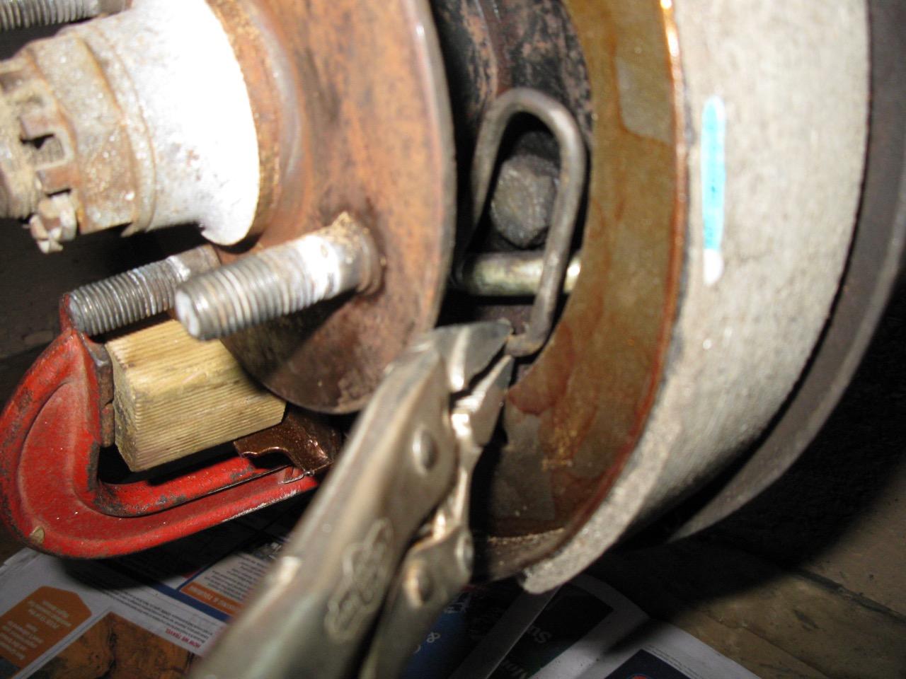 Hi All, This is my first post to this forum and first up, I'd like to thank all those that have come before me and shared their tips and tricks for everyone. After recently completing the Girling Caliper/ Vented Rotor front brake upgrade to my 74' 2002, I decided to tackle the rear brakes as the shoes were pretty worn and I was at maximum adjustment. I'd read about the fun and games with getting that lower "M" shaped spring back on without losing an eye in the process and was a bit sceptical about tackling it myself! I scoured the internet (including this forum) and couldn't really find a super clear explanation so I set about trying to figure one out. I think I've come up with a pretty safe and easy way to get those springs on and I wanted to share what I learned on here. I actually took a lot of video of the job which I'll turn into a YouTube clip when I get a chance but until then, here is the basic explanation of what I did. Tools required: Large flat blade screw driver 3 x G clamps Needle (long nose) Vice Grip pliers 40cm long piece of wood (about 4-5cm wide) small block of wood (3 x 3cm) See pic. Once you've removed the old shoes and cleaned up the drum backing plate, wheel cylinder, hub etc. Check everything is in good shape and the cylinder moves freely and the rubber seals are intact. Release both 10mm nuts on the handbrake cables at handbrake inside car. Turn the 17mm adjusting nuts on rear of backing plate to allow for shoes to be as close to the centre hub as possible. Install new shoes by connecting the top spring between the shoes, attach the handbrake cable and position ends of shoes in the vertical slots in the wheel cylinder. Its a good idea to take a photo of the brake layout BEFORE removing the old shoes! Once the shoes and top spring are all in position, clamp the long piece of wood across the top of the brakes (covering the wheel cylinder) to the backing plate. This will hold the shoes in position while you're trying to manhandle the bottom spring on. Here comes the tricky bit.... Take the big spring and position the LEFT hand end into the hole on the lower left shoe and position the middle of the spring in BEHIND the small central plate. Hold this in position while you clamp the small block of wood over the left hand end of the spring to secure this end in the shoe (see pic). Once the spring is firmly clamped in place, take the screwdriver in your left hand and poke it up behind the hub and onto the top of the small central plate and rest it on the spring. The idea is to apply upward pressure on the screwdriver to firmly hold the middle of the spring from jumping out from behind the central plate. (I used my foot to hold the screwdriver which then freed up both hands to work the Vice Grips) Be strong...! Set the Vice Grips as tight as you can get them on the RH end of the spring which is kind of tucked in behind the right shoe at this point. You should be able to get a grip on the lower "U" part of the spring and then gently (and carefully) pull the spring out over the shoe and downwards until it drops into the hole. BINGO! Wasn't that hard was it! Remove all the clamps and wood etc and check if everything seems to be in position. Slip drums back on and adjust the 17mm nuts on the back of the backing plate until drag is felt, then back it off a bit. Road test the car and repeat the brake adjustment. Don't forget to do the handbrake! I hope this info has helped and here is a link to the YouTube video. Cheers Evan5 points
 -
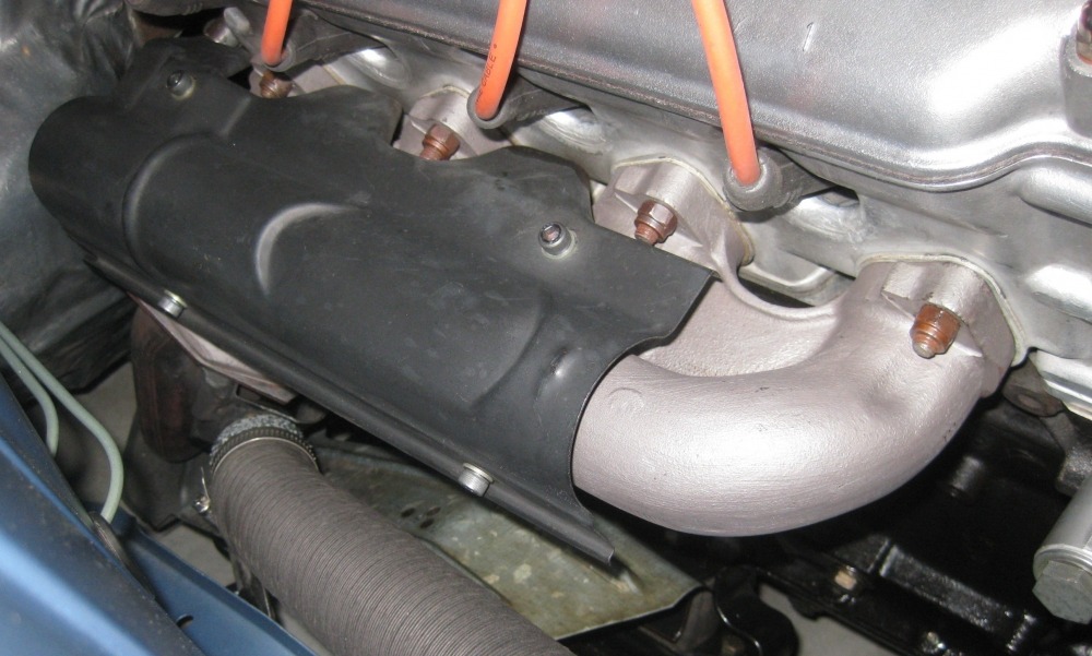 Written by John Aho Monday, 05 September 2005 Installing Exhaust Manifold or Header Studs By John Aho Studs are designed to be fitted only "finger-tight" into their threaded hole in a casting. However, a locking type of nut (PTN, or prevailing torque nut) is often specified to go on the stud. These two facts present an inherent dilemma. The grip of the PTN on the stud can easily turn the stud when you don't want it to (how often have you removed an exhaust manifold nut and had the stud come out at the same time?) With this in mind, the installer may be tempted to over tighten the stud into the hole, to make certain it stays put. This mistake happens a couple of ways: Either the stud gets torqued after it bottoms in the hole, or the stud's shoulder (unthreaded section in between the threaded ends) jams into the surface at the edge of the hole. Some studs have no shoulder (all thread), and some holes have no bottom (through hole). This allows for another problem: with nothing to stop it, the stud can insert too deep. So, why is it wrong to tighten the stud into the hole? Unfortunately, I have even seen it done by supposed "professionals". The way a stud can outperform a bolt in clamping efficiency has to do with the even distribution of stress across the engaged threads. If you torque a stud into a blind hole, you lose that benefit, and concentrate stresses at the first thread in the hole. If you torque the shoulder of a stud against the edge of a threaded hole, you lose the benefit & usually distort the mating surface. It's not as if there is a suitable bearing surface to take the load. Just don't do it. Loctite threadlocker is the answer for securing the stud (for most of our situations), but it's worthwhile to look at the design intent of the purely mechanical fit. Studs require a "fit classification" that provides a very close fit. Common American thread classes include #2 (free fit, general application) and #3 (very close fit). Classes #4 & 5 are actually interference fits, and you won't find them readily available. Metric thread fits are classed differently, using a number to designate "tolerance grade", and a letter to indicate "fundamental deviation" (upper case letter if internal thread). When a class of fit must be provided for mating threaded parts, the tolerance symbols of the internal thread is shown first, then a forward slash, followed by the external thread's symbols (for example, 5H/4h). Basically, ISO metric "6" approximates a UNF class #2 fit. The metric range also includes 4 & 5 (closer) and 7 & 8 (looser). The letter H or h indicates deviation allowance = none. You can get a decent "ball park" on fit class by the feel of threads engaging, but to really measure it is much harder. The major diameter (O.D.) of the stud's thread is not the primary determining factor for class of fit. The pitch diameter (an imaginary cylinder located where the thread width is equal to the space between adjacent threads), which requires a special "thread micrometer" or the 3-wire system to measure, determines the class of fit. The bottom line is you should try to only use metric steel studs designated as 4h. Good luck finding them. The '02 parts book shows M8 x 40 studs, but the length used can vary from 38 to 45 mm depending on availability and/or thickness of the header flange. Be sure to select studs with a shoulder. Customarily, metric steel studs have their nominal length (which protrudes) less than their overall length by approximately 1.25 x diameter. This would mean about 10 mm of thread goes into the head. The last BMW studs I got had about 15 mm to thread in the head, which is even better. The blind holes on the bottom row of the exhaust side are about 20 mm deep, so you won't bottom out as long as you put in the correct (short) end. There's some decent manifold studs used by other manufacturers, if you look around. The Saturn cars use the same size, and have a feature on the outer end that is made to fit a female E-7 torx socket. So what does all this mean to me when I've got an exhaust stud backing itself out of a buggered hole on a 2002 head? You will have to clean out the hole completely to get the Loctite compound to work properly. Getting this done on the car, with the manifold still in place, is a pain. Even with the exhaust out of the way, the top row of stud holes go right through into the head, making them very hard to get clean & dry. To proceed: the loose studs will come right out, and you can "double-nut" to remove the rest. Take off the valve cover and blot away the oil around where the top four threaded holes go through. Carefully use a proper thread chaser to clear out any old threadlocker or other crud. Clear out the debris you've just shoved into the head before it washes down into the sump. Use an aerosol can of brake cleaner to wash out the threads, use a rag pushed tight up against the inside of each through hole to prevent solvent/debris from getting inside. Please Note: The Loctite compound will only work if you do a good job getting things clean & dry. Follow the instructions that come with the product. Try to find Loctite 262 (a bearing supply house will stock it), otherwise use the readily available 271. Again, use as directed: just one drop on each clean, dry, new stud as they go in. After the Locktite has set, reinstall the exhaust with new gaskets, and torque the 8 new copper plated steel PTN to 30 Nm (22 ft lb).5 points
 -
 How To Build the Strongest Small-case Limited-slip Differential For Your 2002. AKA: Late E36 318i/ti Pumpkin into an E21 Open 6-bolt Differential Case. By Andrew Adams of Ireland Engineering Email: a n d r e w a d a m s @ I e m o t o r s p o r t . c o m Website: bmw2002.com or iemotorsport.com Disclaimer: This is not a beginner project, nor is it meant to be a complete diff-bible, and as such, I (or IE) are not responsible for ANY of your screw-ups. There are some topics which are abbreviated both intentionally and unintentionally. Forward: This would not have been possible without the constant teaching from Jeff and Jeremy of IE and knowledge of Rob at Precision Gearing. If this project looks a bit much for you, or you have the money but not the time, call Rob (http://precisiongearing.com/ ). TABLE OF CONTENTS V6.5---------------------------------- – Basics: How a differential works – Basics: BMW Differentials Why the E36 318ti LSD? Different Differential Cases Rear Cover Options – Basics: Performance Options – Differential Rebuild - Tech photo w/ part names - Test break-away - Removing diff from car - Side-cover and LSD removal - Pinion Shaft removal - Cleaning - Pumpkin Break-down and reassembly - Pinion Shaft installation - Pumpkin insertion - Side-covers and Setting Lash Basics: How a differential works.---------------------------- For those who'd like to understand the principles of the differential itself, I've attached some videos that explain it far better than I could (thanks Chevy and Toyota!) Here's a link describing the basics of a clutch-type limited-slip differential (which is what we'll be messing with). http://auto.howstuffworks.com/differential4.htm Basics: BMW Differentials.------------------------------------ BMW uses three different sized differentials. SMALL (168mm ring gear), MEDIUM (188mm ring gear), and LARGE (210mm ring gear). For the sake of this write-up we'll be focusing on the small case limited slip differentials. These are found (as standard or option) on 4-cylinder BMW's in the 2002, E21, E30, and E36 cars. Why the E36 318ti LSD?----------------------------------- The E36 318ti lsd's were the last of the line for smalll case lsd's, and as such were the most capable in handling higher amounts of torque than earlier diffs. This is evidenced in a couple of ways. – The lsd-cap is .5” thick, the thickest out of any bmw/ZF 168mm diff. – The output shaft collars are noticeably thicker than the E21 & E30 pieces. It is my understanding that they are the same size as the pieces on the the medium-case differentials, but I have not verified that. – The ring-gear bolts have a serrated underside for better grip. These address the most common failure-points on the small case diffs, the cap cracking (or the bearing nose shearing), the splines on the spider-gear shafts shearing, and arguably the most common failure point; the ring gears bolts backing themselves out. With this center section I will have the best chance of having a small-case diff that won't blow up when powered by the 6-cylinder M20. This means there is no need to resort to modifying the rear subframe (or paying someone else an obscene amount of money) to fit a medium case differential. Differential Cases--------------------------- -2002 came with 4-bolt side-covers and bolt-in output flanges (with the ’76s having slightly longer output flanges). -E21 EARLY (08/79 and earlier) – 4-bolt side-covers and circlip-held output flanges -E21 LATE (09/79 and later) – 6-bolt side-covers and snap ring held output flanges I’ll be using the late E21 open case for this with the beefier 6-bolt side-covers and 10mm cv-joint bolts (in the vain hope it will matter). You “should” be able to use a 4-bolt open 2002/e21 case if the center section coming out of the case is the same width as the Limited-slip pumpkin. Rear Cover options on the 2002 with small case differential.---------------------------------- -2002 EARLY (mid '74 and earlier) -2002 LATE ‘finned’ -Alpina Finned* -Alpina Chinese knock-off* -Big Billet Cover* -Tap in AN fittings and run a pump/cooler.* This differential will be using the 02 late finned cover, all the fancy options would be overkill on a street car. I want this differential to be well-engineered, not over-engineered. The shorter the gear ratio (higher number [4.10,4.40, etc.]) the quicker the acceleration, but with a reduction of your top speed. There are many differential calculators online that should help you to find your ideal setup. Basics: Performance Options----------------------------------------- Rather than go into this in detail, I'll be straight forward. Unless this is a dedicated track/rally/autox car then the extra money spent is largely wasted. The only thing I'll be doing is increasing the brake-away torque, which I will not elaborate on but you should definitely consider. If you do have a race-car and could benefit from different ramp-angles, added clutches, polished gears, safety-wire, etc. Then please call a 2002 performance parts supplier you trust (do NOT just use anybody and skimp) if you'd like some recommendations then feel free to email me. Differential Rebuild----------------------------------------------- 1 Exploded view of the differential case and its components.------------------------------- 2 Remove the differential from car (see Marshall's excellent writeup ----------------------here …. http://www.bmw2002faq.com/component/option,com_forum/Itemid,50/page,viewtopic/t,373426/ ). 3 Break away:------------------------------------------------------- Prior to disassembly, measure the break-away torque of your differential (how much force it takes before the LSD clutches slip). A good percentage of the used E21 LSD's out there today are worn to the point where they hold barely more than a sticky open diff (sorry for those of you who paid $400 for an non-inspected E21 LSD). If you can twist the differential out-put flanges in the opposite direction with your hands then you've got a very worn differential. A healthy stock e21/e30/e36 small case LSD should take between 25-30 ft/lbs before slipping. By measuring now, it will give you a good baseline indication on the condition of the individual components inside the center pumpkin. I measured my E36 pumpkin to have a break-away of 26ft/lbs, so technically I would be ok if I was to just stick it into the case and call it a day. However, I'm shooting for a bit more than 40ft/lbs. which is about the most I'd want out of a street-oriented LSD. (by comparison SPECE30 medium case LSD’s are limited to 65ft/lbs., and most other 2002 race setups are around 80ft/lbs.) 4 Side-cover and LSD pumpkin removal:------------------------------- First take off the rear cover and drain the oil, this stuff has a rather distinctive smell. Be sure to do this in a well vented area, or near your mother-in-law. Pop out the diff flanges, this might take something rather long (big flat-head screw-driver. crow bar, or bar stock.). To prevent damage to the side-cover, use the bolt heads for leverage. With the flanges out, use a standard seal puller to remove the flange seal out of the cover. Remove the side cover bolts (loosen progressively in a cross-hatch pattern so as not to warp the cover [think head bolts/studs]). With the bolts out gently tap around the side-cover with a thin flat-head screw-driver acting as a wedge; if care is taken you will not leave any lasting marks. As the cover starts to come off you'll see some thin shims, these are important to keep with their respective side as they allow for correct laterally spacing of the center-section inside the case. When you pull the side covers off the center-section will come loose and drop in the case, put some rags underneath to pad the fall or risk chipping the ring gear. String the side cover and shims together while marking the which side of the case they came off of (I simply used a die punch marking one or two corresponding dots) so when it goes back together everything will be in order. If you are swapping in a LSD pumpkin, remove it front it's case in the same manner. 4) Pinion Shaft removal:--------------------------------------- Now that the pumpkin and side-covers are removed you're left with the Pinion Shaft and the case itself. To start you'll need to pop-out the old lock ring on the backside of the input flange, you can remove it with a flathead screwdriver or drill. Now you'll need to loosen the nut and to do that you will need to keep the shaft from spinning. BMW made a special tool that looks like this (if you have one, chances are you don't really need any instruction on how to do any of this). You can easily replicate something to imitate this tool's function. Loosen/remove the nut and tap “in” the shaft from the backside to remove the pinion-shaft. DO NOT take a typical hammer to the backside of the shaft; you will damage it in some way. Use a rubber hammer, and if that proves difficult, use a press. With the shaft removed you will see that the pinion-shaft has the inner roller bearing pressed on it Toss the crush sleeve on the pinion-shaft shaft into the trash. To remove the inner roller bearing from the shaft you'll need to use the press and a strong bearing splitter. If it proves difficult (like it did for me) then use a torch to heat up the bearing a bit. Now let’s go back to the case and focus on the inner and outer bearing races left in the case from the shaft we just removed. Start by removing the circular baffle with a couple good punches with the flathead. Punch out the inner race (preferably with a softer metal rod like aluminum to keep your punch from gouging the insides of the case.) As the race comes out you will see a spacer behind it DO NOT LOSE THIS, it spaces the pinion gear's depth in relation to the ring gear. Each spacer is specific to that particular ring and pinion. Punch out the outer bearing race from the inside You can also use a clawed bearing puller but I found the punch method much easier. With this done the case is now fully disassembled into its sub-components. CLEANING ------------------------------------- With the case completely apart clean, everything thoroughly. Thoroughly degrease the inside of the case; you don't want any muck causing havoc on your new bearings. Ideally, bath the case in a solution of degreaser. You can take some emery cloth (or scotch-brite pad) and rub down the pinion shaft along with getting all the teeth of the ring gear and pinion head. Then use brake cleaner (or otherwise) to make sure no residue is left behind. Any spec of grit can damage of your refurbished diff. Prior to paint I broke out some die punches and stamped the case IE/AA/001 3.64. Pic shows post paint. Prep and paint the case in the paint of your choosing (engine enamel, por-15, etc.) likewise, with the rear diff-flange and side-covers. For giggles I polished the rear cover, do whatever makes you happy (understand that the rear cover helps to dissipate heat so powder coating, painting, or otherwise adding insulation is probably not the best idea in the world.) REASSEMBLY--------------------------------------- LSD PUMPKIN BREAK-DOWN & REBUILD----------------------------------- First I compare both the E21 open center-section and the E36 pumpkin, they are the same height, and therefor compatible with one-another. You'll notice the E36ti pumpkin has a pinwheel on one end, this pinwheel is read by a sensor on the diff case to calculate speed. Since we're not running this sensor, you can remove the speedo wheel (I used a die grinder). If you are changing the gear ratio, remove the ring-gear from the pumpkin. To do this loosen the bolts a little at a time in a crisscross manner (just like head studs/bolts). With all of the bolts removed you will need to use a punch through the empty bolts holes and tap the ring-gear off (be sure to have some rags down for the ring to land on. Now we tackle the case, using a bearing puller (or in my case, a bearing splitter and bench press) pull off the roller bearings from either end. Using the same crisscross method as the ring gear bolts loosen and remove the allan-head bolts attaching top cover to the case. As you loosen the bolts you'll notice the top cover is held in tension by the as the internals expand. (Note the picture still shows the bearing in place, just ignore it)A weak limited-slip (with a low break-away) is simply due to a lack of tension on the internal components i.e. low break-away = worn internal parts = lost material = more space in case = less tension under load. BLOW UP DIAGRAM OF INTERNAL COMPONENTS-------------------------------------- As you remove the cap you will notice 2 smaller washers (#2 & #3), the top piece is the smaller Diaphragm Spring aka Bellview Washer (make sure you see what way direction this goes in, you don’t want to put it back in upside down). The second washer is the Stop Disk, it has two indents on the bottom that allow for oil flow. The first large disk is the larger Bellview Washer (#4), this provides much of the tension in the differential. Inspect the top surface near the inside diameter, a worn Washer will have a wear ridge there, if you can feel a change in height with your finger nail, replace the washer. Next you have the dog-eared Outer Disk (#5), this disk acts like the surface face of a flywheel. It's available in a few thicknesses, with the thickest giving a higher break-away (but go too thick and you'll essentially have a locked diff. with no break-away). Check for any grooves or ridges and replace as necessary. Just as a flywheel you can also “resurface” the side of the plate which faces the clutch plate, just take fine-grade sandpaper (500grit) and scuff the surface evenly. The Outer-Disks on this diff looked and felt smooth, so all I needed to do was a little scuffing. After the dog-eared Outer Disk you have the Inner Disk aka clutch-disk (#6)(and as you'd imagine it functions in the same way the clutch-disk works on the transmission). These clutch-disks have a grippy high-friction material coating on them. If your disk has no or little material left (will feel smooth to the touch) then it will slip much easier, replace it. These can develop a smooth inner ring and still have a grippy outer-ring, if this is the case, still replace it. At the center of the LSD we have the Spider Gears and their housings.(#7, #8, & #9) The spider-gear housing pieces are officially known as the Compression Rings (#7) since they are the pieces that moves out-ward under load which put pressure on the clutch disk “locking” the differential. Like the dog-eared outer disk you can lightly scuff the surface. Just inside and poking out of the Compression Ring, we have the Side Gear (#8) portion of the Spider Gears. The output flanges stick into these so the beefier the better. Check for cracks, if you can, get them magnafluxed along with the other parts of the spider gear and Ring & Pinion. Finally in the middle are the 4 Bevel Gears and shafts (#9). Check them over carefully for hairline cracks. From that point on everything on the bottom half of the case is a mirror image of the top, inspect everything and replace as necessary. Once the guts are all ready, use 2 new allan-head bolts [8x16 10.9] to secure the diff-top. Using a press, install the new roller bearings on either end. Make sure to only put pressure on the bearing's inner sleeve. Ignore that all the allan heads are in place in the pictures. The last thing to do on the pumpkin is to bolt the ring-gear in place. First make absolutely sure there is nothing on either the ring-gear or differential mating surfaces (clean with denatured alcohol or similar). The ring is a snug fit so you might need to warm it up a bit with a torch before sliding into place (Hopefully you’ve waited for the denatured alcohol to evaporate, otherwise torch and alcohol equal BOOM!). Use some longer 12x1.5mn bolts to thread into the ring gear to act as guides as it’s lowered in place. With new bolts (or safety wired original bolts) torque the ring gear bolts down to 110ft/lbs using the slow crisscross method. When they are torqued down apply a dab of paint-pen paint to each bolt edge, this will allow for visual check when you want to make sure the bolts aren’t backing out. (If the paint seal is broke then the bolt has moved.) Bolt down the top-cap with a couple of the allan-heads (not final torque), and check the break-away torque now while it is easy. I measured mine out to 43ft/lbs before slipping; perfect! PINION GEAR INSTALL--------------------------------------------- Tackle the pinion gear assembly first, and the first step is to install the new inner and outer races. These can be rather tight, so it's a good idea to have them sit in the freezer a few hours prior to inserting them. On the inner race be sure to set the spacer/washer from the disassembly in prior to tapping the race in. Start tapping the race in until it sits snug on the washer/spacer (tap in the crisscross method to keep the race from going in sideways). Use a press to install the new inner roller bearing onto the pinion shaft. Slide the pinion from the inside, then from the other side slide on a new crush sleeve, roller bearing, seal, rear output flange, and the nut. Get the nut started by hand, but then attach the BMW special tool (or your equivalent) to the rear output flange and keep tightening with the socket (though you might need to switch to a breaker bar). At this point it's extremely helpful to have a couple of friends on deck to keep the diff from flopping over. The factory manual calls for 25 In/lbs. of rotating torque. As you tighten the Pinion Shaft Nut down you'll feel quite a bit of resistance from the crush sleeve, be sure to stop frequently to rotate the flange/pinion by hand. With every twist the pinion should spin easier. Repeat this process until you hit the 25 In/lb mark continually (that is to say the pinion doesn't loosen as you twist) the final feel is similar to putting a finger in molasses (thick but smooth). mlytle edit - the below is TobyB's method. I have used this way to do the pinion TQ also. several manuals have 25 Ft/Lbs as the tq, but it should be In/Lbs. even that is too high. should do it by feel like a wheel bearing as TobyB describes below. ----------------------------------------- Yeah, it's inch- lbs, that's a misprint. When you're doing it, you'll find that once you start crushing the sleeve, you're pulling REALLY hard to crush it. So you'll cautiously creep up on it- tighten a little, wiggle, tighten, wiggle--- when it gets to the point where you can ALMOST not wiggle, you have to go very slowly- one tighten, all of a sudden, the wiggle's gone, but it turns very easily. THEN you need to turn about 3 degrees more to where you can feel 'some' bearing drag. If you've set up tapered roller bearings before, you'll know it- it'll go 'firm' but not crunchy. If you go 2 degrees too far, it'll get 'stiff' or 'crunchy'- and you get to do it again, with a new sleeve and probably seal. The first sleeve is easy to kill- after that, it's pretty easy to do a good job. ------------------------------------------ With the nut torqued down, tap in your new lock-plate (it will be tight but it will expand into the relief slot on the flange [if you don't bend it in half]). SIDE-COVERS & PUMPKIN INSERTION -------------------------------------- One of the more difficult parts of the entire process is the removal of the side-cover bearing races. Typically a race will have some sort of lip to use a punch or puller on allowing for removal, for some reason the E21 open diff's side-covers have no such access. The only way to remove them is to carefully drill a few small angled access holes on the face of the cover so you can run a punch through and pop out the race. (Then mask one end of the hole and fill with some JB weld). If there's a better way, I'm all ears. EDIT: In the comments section below there are a few other options that have been added! Put the side-cover bearing races in the freezer for a half an hour (shrinking them slightly just as before with the pinion). With the JB weld now dry and the cover's race surfaces clean and flush, take the new race out of the freezer and using your old race as a driver, tap the race in as before. With both side-covers races in, remove each of the old rubber O-rings and replace them with new ones. Press in new out-put flange seals. With your side covers (and their respective shims) ready it's now time to address how to get the E36ti assembly in without any modification. If you try and take the pumpkin and simply slide it in you'll see that it will not fit. Remove the 2 Allan-head bolts you bolted in to secure the pumpkin top-cover. Take care that you don't spill the pumpkin guts. With the top-cover removed there is now plenty of room the slide the pumpkin inside the case. With the case inside, slide in the top cover and simply start bolting the Pumpkin top-cover through the side-cover opening. Use new bolts and some loc-tite, torque the bolts to 25 ft/lbs using the crisscross method, to get that much torque you'll need to slide the passenger side flange in through the case and mount it stationary (bench vice), this will allow you to tighten a bold, back back the flange off, and rotate the pumpkin until all of the bolts are torqued. Now with the pumpkin ready, slide one side-cover/shim on (use a little assembly grease) and tighten down 2 bolts. Tip the diff onto the side that has the side-cover bolted in and maneuver the pumpkin so one end sits in the side-cover race, this will line up the diff so you can slide in the other side-cover from the top, tighten 2 bolts as before. Now you're ready to start testing for lash. Setting Lash---------------------------------------------------------- Please note that the factory manual goes over setting correct lash in-depth using precise measurements. After doing a few diffs via the manual you can start to feel the differences by hand. This is very hard to convey via a technical write-up, but I’ve given it a shot. Lash defines the contact between the ring-gear and the pinion-gear. Too tight and the friction between the gears will be enough that the teeth will start flaking metal and stress-cracks will soon brake the gears. A too-tight lash can be identified by having a contact patch on the inner portion of the ring gear teeth (and there will be NO give when turning the input flange). Too loose and the gear teeth will shear clean off during high bursts of torque (i.e. drag racing, donuts, burnouts, etc.). This is identified by having a contact patch on the outside edge of the ring gear teeth. A proper lash will have a full contact patch on the middle of the teeth and a little give before the gears mesh which can be felt when turning the input flange. To adjust the distance between the gears (thus adjusting lash) we use the side-cover shims . These shims compensate for manufacturing tolerances of the pumpkin and can move it laterally within the case. A thicker shim on the driver's side will set the ring-gear further away from the pinion-gear. A thicker shim on the passenger side pushes the ring-gear closer to the pinion-gear. I used Dicum layout fluid to observe the gear contact patch, you can use any sort of marking paste or fluid. Many shim sizes are still available through BMW and typically cost $8-$10 each. With all that in mind, the total shim thickness for the two shims on my e21 case was.120” I test fit the new pumpkin with each shim as it was originally. This proved to be way too tight, there was no give in the input flange when turning and a test swatch of Dicum on the teeth showed a contact pattern on the far inside. For the next test I stacked both shims on the driver's side (pulling the ring-gear away from the pinion gear), that resulted in too much lash (about 1/4” inch before the gears contacted one-another) but it was better than the first test. My ideal lash was somewhere in between, going onto ETK and converting metric to standard I ordered the thickest shim available (.08”) and a corresponding (.04”) shim to maintain the .120” total thickness. Once the new shims came in I put them on and broke out the Dicum once again. In the initial twisting of the input flange, I found there was about 1/16th” lash before gear contact (near perfect!). Rotating the ring-gear through yielded a nice fat contact patch in the middle of the ring-gear. Lash set, and ready to go. For the final assembly of the side-covers I pulled the 2 test bolts from either cover, added a touch of loc-tite, and torqued down all 6 bolts for each side. As the Piece de resistance I popped on the polished re-drilled output flanges. I'll be using the stock '02 8mm cv-joints for now but will switch the the 10mm E21 cv-joints once the M20 goes in. Lastly was the rear cover gasket and rear cover. With those in place I had a complete, tough, limited-slip diff ready to be installed and broken in. Hope you found this helpful.5 points
 -
 Original Author: Bill Williams Mike taught me a way to bleed the clutch system on a five speed that makes things pretty simple. Get a pump type oil can from your local hardware,dedicate it to brake fluid. Put a section of tubing on it that fits the spout on the oil can and the bleeder screw. Fill the can with your favorite brake fluid, connect the tubing to the bleeder screw, crack the bleeder screw open and start pumping. Have an assistant watch your reservoir to let you know when the reservoir is full and no bubbles. Close the bleeder screw. Bob's your uncle.5 points
 -
 Written by Trent Tilton Friday, 30 September 2005 How to swap a 320i (e21) Alternator onto a non-tii BMW '02s How to swap a 320i (e21) Alternator onto a non-tii BMW '02s By Trent Tilton Parts Needed: 1977-79 320i Alternator. These can be bought new or found at the junkyard. You might want to get new alternator bushings at the same time. Most recommend urethane bushings as they will outlast the stock rubber ones by a considerable margin. Instructions: Disconnect Battery Remove stock 45 AMP Alternator - Remove 3 prong wiring harness and the 10mm bolt that holds the red wire. Remove bottom 13mm nut and bolt from the tensioning arm. Remove the top 13mm bolt. Remove Alternator, and list it on fleaBay (RARE! Original! BMW Alternator! ). Remove the square voltage regulator located next to the relays on the drive side engine compartment. The 320i alternator is internally regulated, so 2 wires only need to be hooked up. The wiring is very easy. The thick red wire goes back on the 320i alternator, on the "B+" post - this wire does the charging. Cut the BLUE wire off the stock 3 prong harness and connect it to the "D+" terminal on the alternator. Hook up the ground wire (brown) just like it was on your stock alternator Bolt up 320i alternator in the reverse of the removal procedure of the stock one. Tighten the fan belt just enough so that you can take the belt between the water pump pulley and the alternator pulley and twist it 180deg. Don't overtighten it because you will kill the water pump bearings. If it squeaks under load (when lights, etc., are on), snug it up a little more. Enjoy brighter lights and fewer charging problems! Take her for a night drive! If you have any questions or comments, please post em on the Message Board!5 points
 -
 I wanted to make this a separate thread from the long one about my fixing Brian Ach's rust-contaminated tii to make it easier for other folks to find the pertinent information without having to look through pages and pages. Pursuant to the other thread, I was trying to nail down a rough running problem in a tii. It eventually turned out to be four rusty injectors, one of which was internally broken, but before I knew that, I convinced myself that rust in the fuel had created a "stuck piston" inside the Kugelfischer injection pump, without really even fully understanding what that meant. There are a few threads that describe the phenomenon, and one that says "it's not really that big of a deal to pull the head off." So I did. I learned so much. Let me try to boil it down and serve it up. Read the Tii Manual, But the Cutaway Photos are Misleading If you have a tii and haven't read "The BMW 2002 tii Fuel Injection System" by BMW of North America (http://www.2002tii.org/pump/pump_guide_v1.pdf) cover to cover, just stop right now and do it. It's an excellent resource. However, it relies, perhaps overly, on those funny cutaway diagrams. The manual essentially says "there are no user serviceable parts inside the pump," so they don't say a word about unbolting the head. Because of this, the manual shows you no photographs whatsoever of the stand-alone head or the pump with the head off, and yet it shows you these odd cutaway views that are a little misleading because, obviously, when you open it up, it doesn't look like that. So here's two pics of the pump with the head off, first with the pushrods exposed (this will be explained more below): and then with the pushrods partially obscured: And here's a pic of the top of just the bare head. The four holes down the middle are where the four suction valves and the Allen key caps on top of them normally go. The two sets of two offset holes outside these are where the delivery valves normally go. The injection lines screw onto the tops of the delivery valves. and the underside, where you can clearly see the bores (cylinders) that the plungers (pistons) run in: The Kugelfischer Pump Is and Is Not Like a Little Engine (engines don't have pistons IN THE HEAD!) The manual says "The injection pump is Kugelfischer Model PL 0 Mini Pump. Its interior is very much like a small engine." Well, it is and it isn't, and we'll get into that. The description in the manual of the basics of fuel delivery is quite concise: "There is a camshaft which drives tappets. These, in turn, drive plungers which are pushed back down by springs. When these plungers move down, suction valves are pulled open and gas is sucked into the cylinders of the pump. Pressure created by the upward stroke of the plungers forces the suction valves closed and the delivery valves open. Fuel is pushed out into the delivery lines and through the injectors. The pressure generated by the injection pump is quite high -- 35 to 38 bar." And that is really all that you need to know about fuel delivery, which is all I was concerned about. The rest of the action that goes on in the bottom part of the pump has to do with enriching, fuel timing, warmup, and other things. But here's what it doesn't say, and what you only learn when you pull the head off: --There's some truth to the analogy that the pump is "very much like a small engine" because the description talks about a "camshaft" and "tappets" and "cylinders" and "plungers" (note it doesn't say "pistons"), and it does have those pieces. --However, the analogy falls flat because there isn't really a block, the "camshaft" and "tappets" are in the bottom part of the pump, and the cylinders are in the head, which is all topsy-turvy from the "little engine" image. How Fuel Delivery Works (the head is pretty dumb, and they're spring-loaded plungers, not pistons) --The manual refers to plungers, but many people refer to them as pistons. And since they run in the little cylinders, people think of them as pistons. But they're not rigidly connected to the camshaft. There aren't little connecting rods and wrist pins or anything. The little pushrods ("tappets") shown in those first two photos of the bottom end of the pump go up and down, and push on the bottoms of the spring-loaded plungers. The tops of the spring-loaded plungers go into the cylinders on the undersides of the head. The springs cause the plungers to retract from the underside of the head. Here are the little spring-loaded plungers. Each is about half the length of my pinkie: And here are the plungers sitting in the head (the whole assembly is, obviously, sitting upside down): --Other than the plungers going up and down, the head is really quite dumb. It's really just passageways. --The suction valves sit on top of the plungers under those little Allen key caps. You can undo the caps and pull the suction valves out with fine tweezers (NEVER USE A MAGNET) and see the tops of the plungers. You can then push down on the tops of the plungers with something non-marring and the plungers will just bounce on their springs. Again, they're not rigidly attached. Here's a photo looking down into the holes where the suction valves sit. They've been removed, so you can clearly see the tops of the plungers. The delivery valves are out as well so you can look into their little threaded chambers, but unfortunately you can't see the passageways. --Fuel enters the head at the banjo bolt at the front (not shown above; not installed) and leaves at the pressure regulating valve at the back (shown above on the back -- right -- side of the head). In between, it's just a straight shot. Except, as the description says, if a plunger is drawing downward, the suction valve allows fuel to be drawn into that cylinder. --As the plunger goes upward, the fuel is put under pressure, and is squirted out a passageway in the side of the cylinder wall. That's right -- fuel comes in at the top but is squirted out the side. Rather unlike a little engine, huh? The passageway goes to the small threaded chamber that the delivery valve for that cylinder is screwed into. --If you do what I did (and, seriously, don't do this) and remove one of the delivery valves and run the fuel pump just to make sure the passageway is clear, fuel will shoot quite spectacularly (clear across the garage, in fact) out of the passage in the threaded delivery valve chamber at about a 45 degree angle.. Why Rusty Fuel Can't Contaminate the Rest of the Pump --Again, the bottom end is where the mechanical smarts are. The head is really kind of dumb, just passageways. Fuel comes in the front, some of is squirted out the delivery valves, but most of it flows out the back of the head at the pressure regulator valve. --As per the other long thread about Brian's car, I can't comment on how rusty gas got into the injectors, because I don't know. I also can't say for sure whether, if rusty gas inundates the pump head, if it should be expected to pass through the suction valves, the passageways in the head, the delivery valves, and train-wreck at the injectors. But I can say that rust or other contaminants in gas really have no way I can see to get into the bottom Swiss watch part of the pump. --And it is very straightforward to pull off the pump head and just blow the passageways out with carb cleaner and compressed air just to be certain they're clean (which is what I did when I had it off). The Fallacy of the Stuck Plunger --I honestly thought I had a stuck plunger because I followed the procedure in the manual to trouble-shoot rough running in one cylinder that seemed to be fuel-related. I determined INCORRECTLY that it wasn't due to the injector (it turned out it was), which led me to rule out the suction valve and the delivery valve and determine INCORRECTLY that it was the plunger. --Reading further and talking with other folks, stuck plungers may be associated with tiis that have sat for years, but are highly unlikely to be associated with well-running cars. That is, the piston can stick from disuse, but it is unlikely to start sticking in a running car that's humming on down the road. --I now know that, if a stuck plunger is suspected, the pump head does not have to come off. You can simply pull out the suction valves, which exposes the tops of the pistons, and use a thin non-marring wood dowel or plastic probe to push on the tops of the plungers, which, as per the photo above, are right there. You're not even sticking anything down a cylinder. This was described in another thread, but I didn't understand how it was possible until I saw that the plungers are not pistons. They're not fixed. They ride on springs. That's why you can just push them down. --You also can pull the belt off the injection pump, rotate the pump pulley by hand, and verify that the tops of the plungers go up and down. They don't move by much -- maybe 1/16" to 1/8" -- but they do visibly move. If you see this, nothing is stuck. So, that should largely prevent you from doing what I did. But... If You're Thinking of Pulling the Head Off a KFish Pump, Remember: --If you have to take the top of the pump off, when you unscrew the four Allen bolts holding it on, the springs on the plungers push the head up. When you lift the head up and out, the plungers will slide out of their cylinders. If you're lucky, they and the springs will drop down into the bottom of the pump. It's not that hard to fish them out. But if you're unlucky, they'll go over the side of the pump and fall down in the engine compartment. Not good. --I don't know enough to know if the plungers and springs are matched for individual cylinders (or matched for delivery and suction valves), but when they fall out, you lose the correspondence of which plunger went into which cylinder, so it's really best not to let it happen in the first place. --When you reassemble the pump and put the head back on, you can try putting a dab of Vaseline or some other gas-soluble grease in each of the cylinders to hold the pushrods in. Or you can curl four fingers around the right side of the pump head and put each finger at the bottom of a plunger, essentially holding the plungers in place while you manuever the head into position. I had to do it a few times so I got pretty good at it. It actually works pretty well. --Knowing this, with practice, when you pull the head off, you could probably undo the bolts, let it rise up from the pressure from the springs, reach around the right side with your fingers, and get them in there and hold the plungers in place. Like I said, I learned a lot... Rob5 points
 -
 Cibié is a French automobile lighting manufacturer founded in 1919. It is pronounced like you are saying C-B-A. There are many Cibié models that are period correct for 1960s and 70s BMWs. In 1969 Cibié was merged with Paris-Rhône, then in 1978 merged with Ferodo and Marchal. These 4 previously competing French auto parts companies formed Valeo in 1980. ROUND LIGHTS: Cibié Super Oscars ( also called 200 series ) - the largest light at 8.5 inches in diameter. 5.5 inches deep. Concave glass lens has a 7" diameter. This is a big light and benefits from bracing rods to prevent shaking. Chrome trim ring is stamped 'SUPER OSCAR CIBIE' at the top. Steel housings are painted industrial gray, though often painted by owners to match the car color. Made in France. Some made under license in Spain and Belgium. Reproductions are available but are easy to distinguish from originals. Hard white plastic covers have black molded lettering. Original old covers have 'projecteurs Cibié iode' molded into them. Newer or reproduction covers just say CIBIE. Cibié Oscars ( also called 180 series ) - 7 inch diameter. 5 inches deep. Concave glass lens is 5.75 inches in diameter. Painted metal housings. Chrome trim ring is stamped 'OSCAR CIBIE TOP' at the top. Three versions of covers. #1 Hard white plastic. #2 black painted metal 'chip pan' grate design with rubber straps. #3 Metal black painted covers with small round plastic 'windows' and rubber straps. Cibié 45 - 7 inches round. Only 2 inches deep. 6.25" flat glass lens. Polished stainless steel housings and trim ring. 4 lens designs ( 2 fog and 2 long range). The 4 designs came in clear or yellow glass, for a total of 8 options. 2 designs of covers. #1 very hard 'white-ish' plastic with 'Cibié Racing Team' sticker. Very easy to break and very rare. #2 hard while plastic with molded black letters 'projecteurs cibié iode'. All the above lights use replaceable bulbs. H1 H2 or H4. These bulbs are easy to source and inexpensive. RECTANGULAR LIGHTS: Cibié 35 - glass lens in yellow or clear. Stainless steel housing and trim ring. White plastic covers. Cibié 95 - black plastic housing HEADLIGHTS: 7" round 'Euro Code' (H4 bulb) Part # 70-28-02 or # 66-70-059 7" round 'Z Beam' (H4 bulb) Part # 70-34-02 or # 66-70-062 7" round 'BIODE' ( two H1 bulbs) Part # 66-70-044 5 3/4" round low beam (H4 bulb) Part # 36-70-039 or # 36-70-050 or # 57-28-02 5 3/4" round high beam (H1 bulb) Part # 36-70-038 or # 57-30-02 REAR RED FOG (high intensity rear visibility): Round - Cibié 40 - red plastic lens. 5.25" diameter black plastic housing. Chrome trim ring stamped 'CIBIE 40' Rectangular - red plastic lens. Chromed plastic housing. 5.5" x 2.5" part # 30-70-037, or kit # 30-70-052 BULBS: The term IODE refers to the Iodine Quartz bulbs used in the lights. Cibié lights use replaceable H1 H2 or H4 bulbs.5 points
 -
 Contributed by Mars Friday, 22 December 2006 Here's how to repair your Tii's dash clock. This method only applies to the early 2002tii clocks (1972-1973). 1974 Model Tii's used a newer electric version. Typically these clocks hold up very well and are quite reliable (although not very accurate when in operation). The most common cause of failure is a fused wire that blows over time. The following below will show you how to fix this most common of causes. This is to be used for reference purposes only. This instructional how to is not to be held liable for any damages caused to your vehicle. Use at your own risk! First thing needed to be done obviously is to remove the clock from the dash. This can be rather difficult as there is limited room to work with. There are a number of ways to try and get in from behind the clock and which one you choose will vary on how big or small your hands are. Access from behind through the glovebox is the most common, but certainly not the easiest. Another option is to move out the console. This is the best way as you will be able to get in from behind the clock and underneath better. The third option for those with small hands (or who have an assistant with small hands) can reach from the top of the dash through the buzzer hole cutout (if your model has the buzzer, not all do) and loosen the screws that hold the clock together. The clock has a small bracket that holds it in place and uses two plastic (or metal) thumbscrews. To remove the clock reach behind with one of the methods above and loosen the thumbscrews. Be ready to catch them as they most likely will fall due to the limited hand room behind the clock. Here is a view of the clock from the floor up and behind the console. The glove box was also removed for this picture. This pic shows the black plastic thumbnail screws that hold the clock in place. Once you successfully loosen the screws the clock will simply pop out towards you. Be sure to grab the bracket the screws go into so it doesn't get lost behind the console. This is another reason I recommend removing the console. After popping it out, simply undo the light bulb, power and negative wires. Take note of which wires go where. The ground wire (brown) goes to the left of the bulb if you are looking directly from behind the clock. The bottom wire (red) with the spade connector is the power wire (12v +). It can be confusing as the ground connection has a 12v engraving below it. This is not an indicator of which connection goes where but rather an indication that it runs on 12v +. This usually confuses most folks. Once out, the next few steps that follow are the most difficult. To gain access to the clock's internal workings you will need to remove the front bezel. This is usually a black trim ring in front but for some it may be silver (such as on the early Ti models). Carefully using a thin flat head screwdriver begin to pry up from under and behind the bezel. Take your time. Patience will be your friend here as you don't want to damage the bezel ring. After slowly going around a few times you should be able to pop the ring off of the clock. Here is a pic of the clock with the front bezel removed. Take note that the ring has notches in it that match a notched area on the inner bezel of the clock. Next, loosen the nuts at the rear of the clock. The nuts are made so that the screws run through them so you will not be able to just use a screwdriver. You can use a small flathead and get at the nuts from one of the sides or a lightweight set of pliers to remove them if they are stubborn. Then, after loosening the nuts slide the clock from out of it's metal casing. Now with complete access to the internals of the clock begin inspecting the clock slowly. Look over the clock near where the copper coil is and around that area but towards the top of the clock. You should see two small tabs. If they are not connected chances are this is the cause of your clock's failure. These tabs normally have a small wire that connects the two and acts as sort of a "fused jumper". All that remains is to solder the two connections back together with a small wire. Use a low temp solder and take your time. I recommend using an 18-20 gauge wire. After that, make sure that you clean the clock well. Use canned air spray to blow out small particles and be sure to check the needles in front as they can sometimes bind and prevent the clock's movement. In the pic to the left you can see where the solder was made and where the tabs referenced above are located. Putting it back together is the reverse of the steps you took above to take it apart. When reinstalling the front bezel, again, take note of the notches and line them up to the clock. With the notches in place I used a small set of needle nose pliers and very carefully crimped the bezel back over the casing. With the notches in place I used a small set of needle nose pliers and very carefully crimped the bezel back over the casing. Here is what it looked like after it was reassembled. Reinstall the clock to the dash. Make sure your ground connections are sound as poor ground is also another common cause for the clocks not to work properly. That's it!5 points
 -
It was my first time visiting Socal Vintage at Woodley Park...saw some nice cars and met a bunch of friendly owners/enthusiasts. Enjoy the pics .5 points
-
 Here are my photos from the event5 points
 -
 Combined two page scans of the front & rear body measurements for a body shop.5 points
 -
 By Mike Self Courtesy of BMW CCA Introduction: If your outside turn signals work, but the inside indicator doesn't (or is intermittent), the problem may be curable by a simple procedure to refresh the flasher relay itself. The problem is that the contacts that operate inside the relay itself rely on a small brass spring, which weakens with age. By carefully bending this spring back into shape, you can save the expense of a new flasher relay to fix the simple problem of the exterior lights flashing but the in-dash indicator not. Procedure: After making sure bulbs, contacts and grounds are clean fore and aft... 1. Unclip flasher unit from its home under the dash near the hood release. 2. Without disconnecting the unit from its wiring harness, carefully pry off plastic cover 3. Engage turn signals, and watch the two sets of relay points inside the flasher box. Big set--outside lights; little one, dash light. Watch as little point set only works one or two times, then quits. 4. Carefully bend the brass spring that tensions the points until they operate reliably. To get it just right, put a load on the electrical system by switching on headlights and heater blower. When interior light flashes all the time the signal is engaged, you've got it. 5. Snap cover back on, reinstall flasher box. Happy flashing! (so to speak)4 points
 -
 Motor drop Take lots of pictures, everything, every angle. Disconnect everything, wires, hoses, distributor cap. You may want to remove the front grills and radiator but I don't think that was necessary. Leave the rear wheels on the ground, well chocked. Raise the front end. Front of car secure on jack stands. Remove the front wheels. Remove the bracket on the strut that holds the rigid brake lines Remove the brake calipers and hang them from something with something. Get the car high enough to get a jack under the front sub-frame. A floor jack or an ATV/motorcycle jack works fine. Disconnect all the shifter/transmission stuff from the tunnel. Disconnect any and all electrical wiring Disconnect fuel lines Disconnect the exhaust at the downpipe Disconnect the strut bearings from the inner fenders. Now, with the sub-frame/motor balanced,lower it slowly, with a friend watching, to make sure everything clears the frame rails. The shifter and distributor tend to be the things that hang up. Once the motor clears and is as low as the jack allows, move your attention to the floor jacks and start moving the car up until the motor will clear the front valance. Pull it out, lower the car. Watch the struts, they want to fall outward. Have someone hold them or bungee cord them to something. Down down down out away Motor plant Mating transmission to motor the hillbilly way Motor plant today with the help of Bill Riblett Pick a nice cold day to work..... Mate the transmission and motor Mate this to the sub-frame Balance sub-frame on jack Lift car far enough for the motor, sub-frame, jack to go under the front valance. Move the motor under the car. Eyeballing it to make sure everything will clear, line up the shifter. Lower the car as far as you can, slowly, having a friend to watch everything. The car should either go so slowly you can hardly see it move or lower it a bit at a time, stop, look, lower, stop, look, you get the picture. Now raise the motor until the sub-frame mates to the frame rails. (Watch and align the strut studs through the inner fenders.) Use a big punch, 10incher, to line up the holes in the frame rail and the sub-frame. Secure the bolts and tighten. If these fight you, get longer bolts of the same diameter and pitch. Use the longer bolts to get things lined up. Pull the sub-frame and the frame rail together, when you can, change out the longer bolts for the properly sized bolts Secure the shifter stuff and transmission mount and support. Make sure the speedo cable is inserted before the transmission support it put into place. Reattach the brake line brackets and the calipers.4 points
 -
 Contributed by Tilux Saturday, 07 October 2006 There are two locking "tabs" that hold the bottom seat in place. Pull up hard on the bottom seat while pushing it back, too. Once removed you will see two curved pieces of steel that lock into the back of the vertical kick panel about one third in from either side. Remove the bottom seat cushion. Now, look under the vertical back seat portion and you will see two metal tabs with a Phillips head screw through a hole in each one; again, about one third in from either side. Back the screws out and jiggle the seat upwards and out.4 points
 -
 How to build your own LED (round tail) tail lights for around $100! Preface: There are a few things you need to know before starting this project! 1. Light output- Yes these are really bright, but no they do not look as bright as the original bulbs when compared side by side, although they are much much brighter. The reason for this is the way the light gets spread around in the tail light bezels. With the stock tail lights, they use regular bulbs and the brightness of the bulbs is directly affected by how shiny the surround they are in is. By bouncing the light around in the housing, it gives the appearance of being pretty bright! However, LED’s do not use this concept. LED’s have a set degree (angle) of light output which is determined by the size and type of LED bulb, and can vary anywhere from 20*-360*. For this reason, they generally do not light up surrounding areas inside the tail light housing like the standard bulbs do, and it can make them seem less bright, but with the proper type of LED for your application they will much look much brighter than the stock assemblies like these do. 2. Time it takes to build these – Believe it or not, it takes and extremely long time to make these by hand. I timed how long it took me to build my final tail light assembly, from the time I pulled the stock tail light off the car, to the time the led’s were built and re-installed and working inside the car. It took approx. 14 hours solid of work, for all of the lights in the one tail light, and that was after I developed the most efficient way to put them together, and didn’t have mistakes or issues to go back and fix. It will eat up a weekend and then some making these… so be aware! 3. Cost- Although it cost me way more than $100 to develop get these the way I wanted them, if you buy wisely, you can build them for about $100 or less. It is easy to spend way more than that if you go crazy and buy super expensive led’s, and buy all your resisters from radio shack etc. This write up also assumes you already have a specific arrangement of tools. If you do not have a tool listed, and cannot borrow one, you’ll need to consider that cost as well. I will give the sources I used to purchase my materials along with the prices of everything so you can see what you’re getting into before you start. If you are ok with all of the above then you are ready to start building! STEP 1: CLEAN WORK AREA You are going to need to set aside a work bench, table, or something solid to do this work on, you are going to have a lot of little things flying around that you will need to be able to keep up. Also be sure your lighting is good. It’s really frustrating to work on this stuff with poor lighting (I bought this little $7 fluorescent light at Wal-Mart for this reason). STEP 1.1 -PLACE TO STORE EVERYTHING! You are going to find you have a lot of stuff that is going to need to have a place to live while you’re working on this project. I found these little plastic drawers at Wal-Mart for $2 (MADE IN US!) they are great for storing little bits and pieces of stuff like this. I also have some file cabinet space for all my wires, big tools, and oem style wire connectors. STEP 2: GATHER YOUR SUPPLIES AND PARTS NEEDED I have gathered a list of parts and supplies that you will need for this project, I recommend getting all of them before starting this, so you will have less lag time waiting for things to arrive or having to stop what you’re doing and running to town. LEDS: 144 Red 5mm Superflux LED’s (for tail and brake lights) ~$40 for (200 pieces) 32 Red or yellow 5mm Superflux LED’s (for turn signals) ~$15 for (50 pieces) 78 White 5mm Superflux LED’s (for reverse lights, trunk lights) ~ $20 for (100 pieces) I purchased my LED’s from Niktronix on eBay, they have super fast FREE shipping, he’s based in the USA, and they have great customer support. You can get 100 of the same type of leds for half the price ($10 instead of $20), but they ship from CHINA and take several weeks, and lets face it if I can support someone in the US instead of China ill pay more!. I recommend getting the 5mm “Piranha” Superflux dome type leds. They are the brightest leds for your bucks (and the best suited for this type of application). Anything much brighter would need more complex boards made for them. I recommend getting more than you need, just because shit happens… Link>> http://stores.ebay.com/Niktronix-LED-and-Game-Specialists/Piranha-Superflux-5mm-Dome-/_i.html?_fsub=2126951012&_sid=43968882&_trksid=p4634.c0.m322 RESISTERS: The cheapest thing you will need is resistors for your tail lights. We are going to need: 46 220 Ohm ¼watt resisters w/ 5% tolerance – for brake, tail, turn, trunk lights (>$5 on eBay) 18 68 Ohm ¼ watt resisters w/ 5% tolerance – for reverse light (>$3 on eBay) You can buy these resisters at your local radio shack, but with the quantity you need, it will cost way more than getting them on eBay. At Radio shack they are $1.09 per 5 resisters…that’s a lot of cash. Get them on eBay, they will be much much cheaper and just as good. 220 Ohm Resister link (BE SURE TO GET 220Ohm NOT 220K Ohm) http://www.ebay.com/sch/i.html?_nkw=220+Ohm+1%2F4+5%25&_sacat=0&_odkw=220+Ohm+1%2F4+watt+5%25&_osacat=0&_trksid=p3286.c0.m270.l1313 68 Ohm Resister link (BE SURE TO GET 68Ohm NOT 68K Ohm) http://www.ebay.com/sch/i.html?_nkw=68+Ohm+1%2F4+5%25&_sacat=0&_odkw=220+Ohm+1%2F4+5%25&_osacat=0&_trksid=p3286.c0.m270.l1313 SOLDER, WIRES, HEAT SHRINK & EVERYTHING ELSE: SOLDER: RadioShack brand .022” Silver bearing rosin core solder ($6.99) http://www.radioshack.com/product/index.jsp?productId=2062717 This one roll will be WAY more than enough, I’ve barely used half of it and I’ve made a ton of stuff! WIRES: Pull-a-part is your friend here. You can go to any pull-a-part and get as much wiring stuff as you want for $7. This is the most cost effective way to get the wires you’ll need for this project, but you can also get some circuit board small gauge (22) wire from RadioShack, and that helps thing go easier. Pull-a-apart wires and OEM connectors galore - $7 RadioShack 22 Gauge wire rolls (75ft) – (optional $7.99) http://www.radioshack.com/product/index.jsp?productId=2049745 HEATSHRINK: A Necessary item if you are soldering any wires. It comes in a million different sizes, but the two sizes I used were 11/64th and 10mm. Harbor Freight Heat shrink 2 8ft rolls of 11/64th ($3.58) http://www.harborfreight.com/11-64-inch-x-8-ft-red-heat-shrink-tubing-66768.html 1 5m roll of 10mm ($2.99) http://www.harborfreight.com/10mm-x-5m-heat-shrink-tubing-98067.html EVERYTHING ELSE: Perf Board looks like this: You will need some unless you want to make your own out of cardboard, or use something else (non conductive) to mount the leds on. (seen it done) RadioShack sells it for $3 per 6x8 sheet, you’ll need two. ($6) Glue sticks- you will need quite a few, I got a 25 pack at Wal-Mart for $3 TOOLS Here is a list of tools I recommend having for this project, although you may find that you can use other thing to replace what I have listed (i.e. normal drill instead of drill press etc.) • Side Cutters • Wire Strippers • Soldering Iron • Hot Glue Gun (or silicon epoxy) • Heat Gun • Drill Press or Drill • Test leads • Precision screw drivers So there you have it! $110.56 for everything listed here that you’ll need! NOW ON TO THE ACTUAL PROJECT! STEP 3: MAKE A TEMPLATE Your first step is to make a template out of cardboard that sits far enough down in the tail light bucket for the leds to clear the tail light lens. This will take some time. Be sure to watch out for the mounting hole in the corner of the tail light section, and plan accordingly. After the templates are made you can transfer them to your PCB (Perf) board and cut them out. I used side cutters for this, but it may be easier to use a dremel cut off wheel. Be sure to mark top and bottom, as the board won’t always fit in the space as nicely if upside down (ask me how I know). STEP 4: DRILL OUT PCB HOLES FOR LEDS This step is quite annoying, but you have to do it if you want to use this style of PCB board. You’ll need to lay out all the leds on your board in the pattern you want them in, and mark the holes on the bottom where the legs stick through. You’ll notice the legs don’t push all the way through, that’s why we have to drill them out. I'm lucky and happen to have a drill press on my desk for this very reason, if you don’t not have a drill press, this will be a bit of a faff. I'm not sure what size the drill I used was, but you’ll only need to drill them a tiny bit larger. Holes drilled LEDs sit flush now STEP 5 PAINT N’ TEST After drilling the holes, I chose to paint the boards with some “chrome” paint to make them look more professional, but you don’t have to. DO NOT USE ALUMINUM TAPE ON THESE BOARDS INSTEAD OF PAINTING! I tried using this because it was so reflective, but it messes up the current flow and the leds WILL NOT WORK. While yer paint is drying, now is a good time to test your leds to make sure they all work before you put them permanently on the board. I use a 3V button cell battery to test them (available at any AutoZone) To test each LED you need to know which legs are positive, and which legs are negative. In this picture we are looking at the side of a red LED. On the left side is the thin anode (+) and on the right is the thicker cathode (-). MEMORIZE THIS! It is crucial to getting them put in the right spot on your boards. Touch the corresponding sides to the 3V battery and it should light up. On other styles of LED’s, they usually will have one leg longer than the other, the long leg is usually negative. STEP 6 LAY ‘EM UP Now that you’ve tested all the leds for this board, we can put them on knowing that they will all work if we do everything correctly. Now we can put the leds where they are going to stay. These leds have four legs on them; we will only be using two of them (one + leg and one – leg). This helps make things half as complicated when we are connecting everything. The reason there are four legs is so they can be used on high vibration applications where they need the extra strength, but it doesn’t affect the light output or longevity. I found the easiest way to set the up on the board was to make the positive leg face the inside (closest to the turn signal) of the board like so. I just cut the extra legs off with side cutters We are doing 9 rows of 4, each row independent of the other. Be sure to put all the leds in with the same orientation as shown above. The pattern of the legs should be + - + - + - + - , with the positive starting on the inside, negative ending on the outside of the board. On the back side we will push the first positive to the side, and then push the legs down, so that each positive is attached to the negative next to it. Leave the last negative to the side as well. Do the same thing for the next 8 rows.. The back should now look like this And your board will look like this! Test fit constantly STEP 7 SOLDERING TIME! Now that you have all of the positives and negatives where they need to be, now you can solder them together. Make sure the legs are pushed all the way through before doing this! Also – the legs of the LEDs are sensitive to the heat from the soldering iron, try it keep it touching the leds for as short a time as you can, it will roast your led if you heat it up too much (never had this happen, but they say if you leave the iron on it for 5+ seconds, it will kill it). In order to solder them together, all you need to do is roll out some of your silver bearing solder, lay it on top of the two legs you are soldering together, touch your iron on both the solder and the legs, and watch it flow and connect the two. Leave the legs on the ends alone for now. Once you’ve done that, you should have something that looks like this> STEP 8 RESISTERS Next you'll need to gather up 9 of your 220 Ohm resisters (THIS IS FOR RED LEDS IN ROWS OF 4 ONLY). They are the ones that have the following stripe pattern – red red brown gold(may not be gold if yours have a different tolerance) If you did not use the same led pattern I did (don’t have rows of four) you can figure out what resisters you need by going here. http://led.linear1.org/led.wiz Look at the specs for the leds you bought and fill it out accordingly. Where you put the resisters is up to you, but you need to consider a few things first. • The resisters cannot be touching any other connections. • You must position the legs in a way in which you can attach a wire, again without touching anything else The way I have this layout set up is so you have plenty of room on the outside portion of the board for your resisters. You will need to have one leg of the resister connected to the negative led leg you have left on the outside of the board. With this PCB board, you will need to leave 3 holes between each leg of the resister for it to fit properly. Tuck the resisters leg under the legs leg so you can keep track of where it needs to be. I usually leave the remaining leg sticking straight up, it is the leg you will be soldering the wire to. Solder your legs to the negative led legs after trimming them to the appropriate length. Should look something like this now Now that half of the resister is soldered to the led it will be a little easier to work with. Bend the remaining leg down and place it somewhere that will not contact anything on the board and trim to about ¼ inch. This is the leg you will be soldering your wires to. I used the small gauge RadioShack wires for this. Cut 9 pieces of wire about 2-3 inches long, and strip a small bit on one end to connect it to the resister. Now “tin” your wires to prepare them for soldering to the resisters. Put your tinned wire on the board next your resister leg, with the wire facing the middle of the board (this will make it easier to fit in the tail light bucket). Solder them together! Check all connections to assure they are soldered together properly and will not come loose! Should look like this when you’re done Next I go ahead and hot glue this section of wires since they can move easily. Let it dry completely before you move on to the next step. Next you are going to bundle these together, cut them to an equal length, and strip the other ends of these wires in a way that you can twist them together in pairs of three (see pic) I know it looks ghetto, but next you are going to solder them together into to one solid wire. Get your handy dandy pull apart OE bmw wires and choose which wire color you want to use, I chose brown with white dashes. Cut these 3 wires to be about 8 inches each, so you’ll have plenty to work with when you pull it through the tail light. Solder them to your wire bundles. Again, pull on and bend the connection to make sure it is solid. Now slide a small piece of your 11/64’s heat shrink over the part you soldered, and shrink it! STEP 9 WIRE UP POSTIVE LEGS We are going to follow the same process above to hook up wires to the positive legs. On this side, however, we will not need resisters. Simply cut your small gauge wires, strip them, solder them to the positive legs on the leds, join them together, and solder your 3 long wires ( I used blue with white dashes) to those bundles and your good! STEP 10 TEST YOUR BOARD This is possibly the most fun step. Take your two long wires, strip the ends of all three wires, twist them together and clamp on to them with your test leads. If you hook them up backwards you won’t hurt anything, they just won’t light up. In this picture the brown is -. Hook the other end of your test leads to a 12V battery and watch your board light up! I used mine to light up the hallway (and the dog) Exciting isn’t it? All that hard work paid off! STEP 11 SEAL UP YOUR CONNECTIONS Now that all the wiring is done, you can either use hot glue or 5-minute epoxy to seal up all your connections and to ensure everything stays where it should. Hot glue is much better to use for this, because if you have an issue you can melt it and fix your problem, and it’s easier to apply. Once that has cooled, I used my 10mm heat shrink tubing on the base of the long wires so that they are protected when you come up through the tail light hole. Now a sharp eye will notice that I have removed the original tabs that used to push on the bulbs. The reason for this is because I don’t want that tab rubbing against my wires that are running through there, and I have no interest in using these buckets for OE bulbs again anyways. You can keep them if you want. STEP 12 REPEAT FOR BRAKE, TURN, REVERSE AND TRUNK LIGHTS. I'm not going to go into detail on the process for the remaining light, because you do the exact same thing. You will use your 220 Ohm resisters for the brake, turn, tail and trunk lights, one resister per row of 4 leds (or one row of three for the trunk light). You will use the 68 Ohm resisters for the reverse lights, one for each row of 4. I'm attaching all the picture I have from building the remaining boards below, and will comment if there is something you need to watch out for. At this point you may notice that your white leds do not have the same type of anodes and cathodes inside them. Looking from the side this is what you’ll see So how can I tell which on is positive and which is negative? Look on the bottom of the LED The left side is smaller, positive, and the right side is wider, negative. Be sure to double check all connections before hooking them up the legs to each other, it is really easy to mix them up. After seeing all of that, you’re now ready for the last steps of this project (hopefully) STEP 13 SECURE BOARDS IN TAIL LIGHT BEZEL Assuming you’ve made all the boards at this point, you’re now ready to put them in their place in the bezel. I used hot glue for this as well. You are going to want to push them as far down in the bezel as possible; making sure the board is flat when you’re done. After doing this, I would test them again to make sure all the connections are still good! STEP 14 READY YOUR CONNETIONS FOR CAR INSTALLATION At this point, there are several directions you can go. You can attach spade connector to your wires and plug them right up to your OE wiring harness, or you can ditch all the crappy spade connectors like I did, and replace them with a modern style (5) wire connector. You can grab these all day at your local pull-a-part. I found some that have 5 wires going in, 5 wires going out, giving me the number I need! I used one 5 wire connector for the positive wires, and one five wire connector for the ground wires. Regardless of which you decide to do, you will need to cut the wires that are running out of the back of the tail light bucket to be the same length. After doing that determine which is positive and negative. I did this by striping the wires, twisting the like colors together from each board, and using the test leads to determine which ones which. I then tied a zip tie to the negative on all of them so I didn’t get confused. I then soldered the each like colored bundle of 3 wires together, neatly connected them to a wire coming off of the 5 wire plug. It doesn’t matter which on connects where at this point. Once in the car you can choose how you want to connect them to the original wires, I soldered them all. Here’s how it looks before I tucked it away. You’re now ready to install it in the car! But wait! You want to actually be able to see the pattern of the led boards you made, and get all the brightness instead of just some of it? No fear! You can turn your led light from looking like this behind unmodified lenses; To THIS! Here’s How! FINAL STEP MODIFYING TAIL LIGHT LENSES Like I said, this step is optional, but you will be much happier with your lights if you do this. What we are going to do is remove all of the reflectors in these lenses, so that LEDs have less plastic to penetrate through. Here is a side by side of a before (left) and after (right) There are little plastic welds that hold these reflectors in, just use some side cutter to snip them off for the brake and reverse portions, and pry with a small screw driver, then lift out with some needle nose pliers. You will notice some sealer around the tail light portion… This is the most difficult to remove, but a heat gun will help quite a bit (just don’t get it too hot!) Eventually it will come out. Now is also a good time to unscrew that little flat head screw on the edge of the turn signal lens to take the chrome bezel off and shine it back up. Install these along with your new LED tail light buckets and you’re done! (with one side at least ) Glamor pics The weird thing is, in these pictures the lights look like a blob of light on the back of the car, but when your standing there looking, they look like the pattern I made the LED boards in. Guess I need to get a better camera. This video is probably your best proof.. [CLICK] Reverse Lights Stop Lights4 points
 -
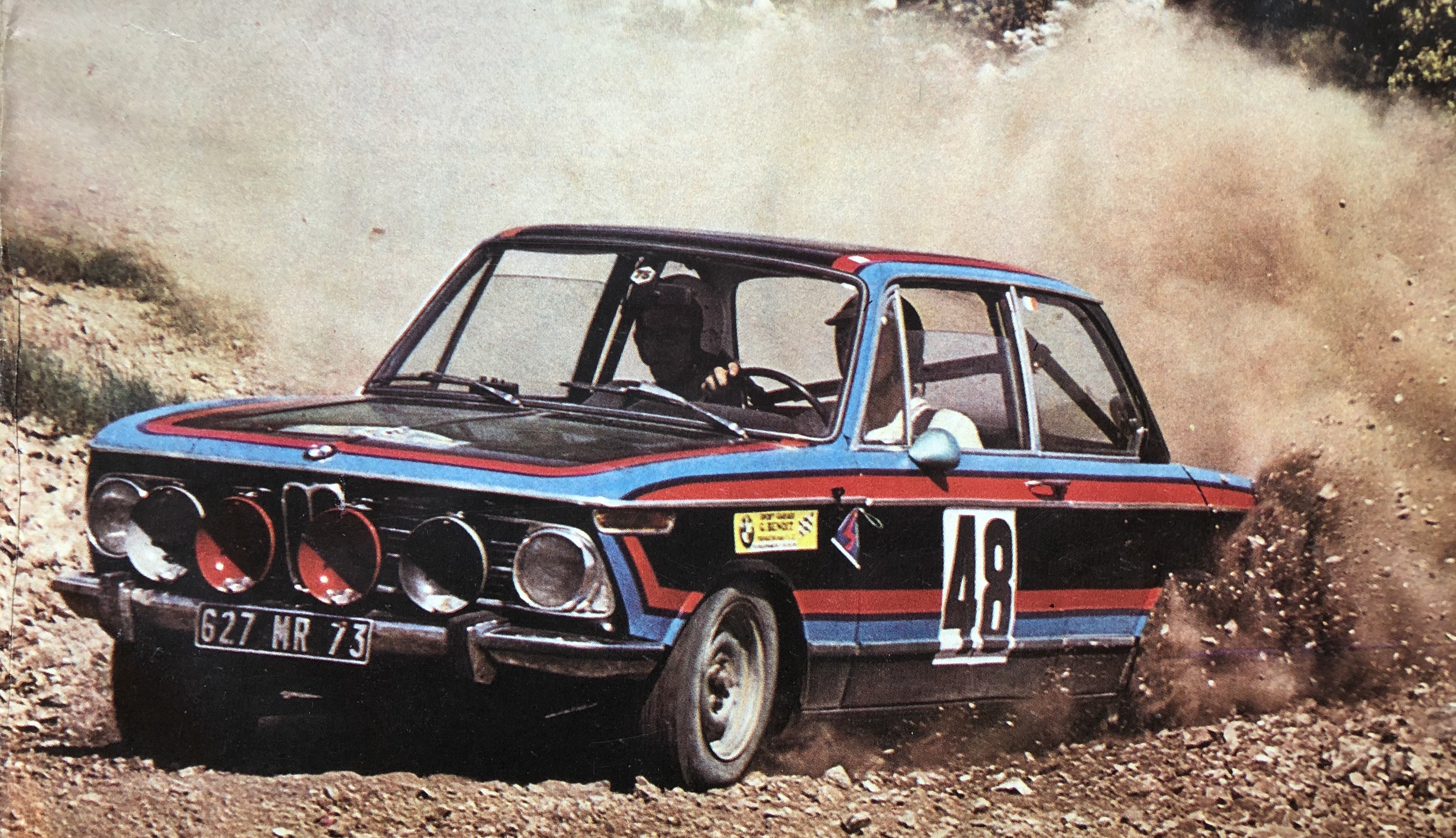 Archive photos of competition BMWs. Rallye, track, endurance racing, and hill climb cars of the early 1970s. Not a 2002, but the '70s fashion is priceless...4 points
 -
 The 24 Heures du Mans For many car builders the 24 Hours of LeMans endurance race is the ultimate test of performance, reliability, driver skill and pit stop strategy. Organized by the Automobile Club de L'ouest, it has been held at the Circuit de la Sarthe in LeMans, France since 1923. BMW first entered the race in 1937 with a single 328 roadster sporting a 2 liter straight six. Disappointingly, it only completed 8 laps. Lessons learned, the proud Bavarians returned in 1939, the last running of the race before the outbreak of WWII. This time they brought a team of two 328 roadsters and one aerodynamic 'touring coupe'. They swept the 2 liter class, taking first, second and third. The team celebrates its 1939 sweep. The 'touring coupe' took first in class after 236 laps. Roadsters finished 2nd and 3rd. Fast-forward 33 years. In 1972 a 2800 CS was entered by the Freilassing, Bavaria based Schnitzer team. Even with experienced drivers Hans Heyer and René Herzog at the wheel, the CS failed to last 24 hours. This was the era of fierce track battles between well-financed BMW and Ford of Germany. 1973 saw the BMW Motorsport team field three CSLs against the Ford team of V6 powered RS Capris. At the end of a grueling race the 3.0 CSL of Hezemans and Quester emerged victorious in the 'Touring Special' (TS) class. The three Fords had all broken, but so had the other two BMWs. The Bavarian manufacturer repeated the win for a second time in 1974. The CSL of French drivers Aubriet and Depine took the Touring class laurels, outlasting the Shark Team Ford Capri of Guerie and Fornage. Both teams would be back the next year for a rematch. Which brings us to the year in question - 1975. Surprisingly, the one and only year when a BMW 2002 was entered at LeMans. The unsuccessful Team Schnitzer 2800 CS entry of 1972. The 1973 TS class winning 3.0 CSL of Hezemans and Quester on the crowded pit lane The 1974 CSL of Aubriet and Depine gave BMW its second TS class trophy. 1975: The 43rd running of the 24 Hours Sponsored by Gitanes cigarettes. Most of the 80,000 spectators got a free pack. BMW eagerly anticipated a third consecutive Touring class trophy. Aubriet and Depine were back in a powerful 3.5 liter 3.0 CSL, hoping lightning would strike twice for them at the revered 8.5 mile track. A second factory CSL was driven by American Sam Posey along with Frenchmen Hervé Poulin and Jean Guichet. It was the very first of BMW's legendary 'art cars'. It wore a vibrant primary color scheme designed by American abstract expressionist Alexander Calder. A third CSL to be driven by experienced 2002 driver Aime Dirand was officially entered but did not materialize. Instead, the third and final BMW entry into the Touring Special class was a privateer 2002ti. This unlikely and remarkable car was the culmination of effort by a driver from France, an engine builder from the tiny Principality of Liechtenstein, and a little help from a certain Bavarian factory in the form of a forgotten project. DANIEL BRILLAT Note the Heidegger and Kleber patches on Brillat's driving suit. The 2002's road to LeMans 1975 actually started in June of the previous year. In '74, Daniel Brillat found himself the lone French driver on a Swiss team. The team had entered the 24 hour race with a tube frame Chevron B23/26 powered by a Ford Cosworth 1.8 liter 4 cylinder. Running 4:13 laps in the S 2.0 class, the Cosworth lost a piston ring and was a DNF. Brillat was born at the end of WWII in the village of Vieu, in the Rhone-Alpes region of France near the Swiss border. He may have been born in the crisp mountain air but he had gasoline in his blood. Like any French boy who loved cars, his dream was to win at LeMans. Justifiably disappointed with his '74 DNF, yet equally motivated, Brillat contacted a skilled engine builder he had heard about in the quaint town of Triesen, Liechtenstein. MAX HEIDEGGER OF LIECHTENSTEIN The tiny Principality on the border of Switzerland was home to Max Heidegger BMW. Herr Heidegger built competition 2002s mainly for hillclimbing and ferocious versions of the M10 engine for Formula 2 cars. Monsieur Brillat wanted one of Heidegger's potent and reliable F2 specification 1990cc motors for a car to contest the LeMans S 2.0 class. But what chassis to put it in? Heidegger and Brillat discussed the goals and financial limitations of the project. Brillat brought with him a useful sponsorship deal from French tire maker Kleber, but sadly not an unlimited budget. The tubular race chassis of the S 2.0 class were out of reach so the Touring Special class was considered. But TS was the domain of the six cylinder CSLs and Capris. Being a BMW dealer, Heidegger had heard through the grapevine of two factory 2002ti chassis fitted with M12 F2 specification engines. He put feelers out to Munich about a possible LeMans attempt with the venerable 4 cylinder. Combined with a stiffened, lightened 2002 shell, he thought it would be capable of being fast enough to qualify for the race and sturdy enough to run the full 24 hour gauntlet. The factory F2 prototypes featured very thirsty Kugelfischer injection. The factory had considered such an option but was focussing on the glamorous CSLs and their high-profile battle with Ford. But knowing Heidegger to be a loyal BMW representative, and a very serious builder of equally serious 2002s, they relented and sold him and Brillat one of their 2 prototypes. The abandoned project was dusted off and trucked the 150 miles to Liechtenstein. INTO THE WORKSHOP Heidegger completely stripped the factory car down to its individual components and rebuilt it to the strict ACO specifications. French sanctioning bodies love their rules and many cars have been disqualified from LeMans for not following them precisely. Max had ideas, borne from experience and ingenuity, of how to squeeze every performance efficiency from the BMW engine and chassis. With a full roll cage, chassis bracing and high capacity gas tanks installed the car had to meet a minimum weight requirement of 2200 pounds (1000 kilograms). New for '75 was a requirement to complete at least 20 laps between refueling stops. During pit stops and driver changes the engine had to be turned off and restarted under its own power. Heidegger relocated the alternator so it would be driven from the driveshaft, reducing load on the forged crank, high compression engine. Heidegger M10 F2 spec engine The expertly ported and polished cylinder head was topped with a ribbed aluminum valve cover proudly displaying the builder's name. Underneath, the revised cams worked in perfect unison with lightened, enlarged valves and springs. Intake came courtesy of dual Italian Dell'Orto side-draft carburetors mounted to custom cast manifolds. Ceramic coated tubular headers were smoothed and maximized in diameter for optimal flow of the spent racing fuel. All this effort resulted in 260 bhp at an 8500 rpm redline. 130 horsepower per liter, 2.1 bhp per cubic inch. Impressive, but could it keep spinning for 1440 relentless minutes? Given Heidegger's literal track record of reliable F2 engines, the outlook was bright. Further tipping the scales in favor of success was the enthusiastic cooperation of Kleber tires. They found the ideal rubber for the 2002's wide magnesium ATS wheels, perfectly housed within handsome box-flared fenders. Extensive tire tests were conducted on Brillat's home turf of France. Daniel was immensely pleased with the outcome of Heidegger's and Kleber's tremendous work. Now to the task of assembling a capable team of endurance drivers to match the capabilities of the car. A TEAM OF DRIVERS ACO rules stipulate a minimum of 2 drivers per car. 29 year old team boss Daniel Brillat picked a friend from Switzerland to join him behind the wheel. Michel Degoumois was an aspiring 25 year old driver from the beautiful Swiss city of Geneva. It would be his first appearance at LeMans. Together Daniel and Michel would drive in shifts to cover the long day of racing. At the last possible minute, a third driver was added to the roster. This driver brought significantly more experience to the team. Achieving the dream of all Italian boys with motor oil in their veins, Giancarlo Gagliardi had raced for two prominent Ferrari endurance teams. By age 31 he had driven for both Scuderia Filipinetti and the famous N.A.R.T. (North American Racing Team) of Luigi Chinetti. Like Brillat, Gagliardi had suffered the indignity of a DNF at the '74 LeMans, but in his case with a Ferrari in the top S 3.0 class. Gagliardi was once again to drive a NART Ferrari in the '75 race. However, the ACO butted heads with NART boss Chinetti and he pulled out his entire team of four formidable Ferraris just hours before the start. This left the talented Italian driver available to join Brillat and Degoumois. Swiss novice Michel Degoumois Late addition to the team was veteran Giancarlo Gagliardi from Italy Gagliardi was supposed to drive this Ferrari Dino 308 GT4. When the NART team withdrew it left him looking for a ride. QUALIFYING Qualifying for the ’75 LeMans was severely complicated by new fuel consumption regulations introduced by the ACO. A response to the historic OPEC fuel crisis of the time, the rules proved to be an unpopular gesture of concern and resulted in LeMans being dropped from the world championships. Entrants had to prove they could cover 168 miles (20 laps) without refueling, then run a qualifying lap fast enough to claim one of the 65 spots on the grid. For the 2002 this meant driving for one hour and forty minutes under the watchful eyes of the ACO scrutineers without a fuel stop. With that task accomplished during the daylight, qualifying laps then had to be taken at night. These far-from-ideal requirements caused much consternation among the teams and were the cause of Luigi Chinetti's argument with the ACO. He subsequently pulled all 4 of his NART Ferraris in protest of the qualifying procedures. With help from its Dell'Orto carbs the Heidegger car passed the fuel economy test. It then covered the 8.47 mile (13,640 meter) course in 4 minutes and 47 seconds. An average speed of 106 mph (171 kph). It earned the 65th, and final, place on the starting grid. It had beaten out two other TS cars for the final spot: one of the Shark Team Ford Capris and a Chrysler Hemi 'Cuda which struggled with a 5:15 lap time. The number 94 Shark Team Capri couldn't match the pace of the 2002 and didn't make the cut. The Chrysler V8 'Cuda would seem an unlikely member of the TS class. De-tuned to meet the fuel consumption requirements, it was way off the pace. Three other Touring cars were entered on paper but failed to appear: the #92 BMW CSL of Dirand, the #96 Ford Capri of Bonnemaison (who dropped the Capri in favor of a GT class Porsche 911), and a Mazda RX3 (#97) with an all-Japanese team of drivers. From a possible field of ten Touring Special entries, only 5 had jumped through all the hoops to qualify and race: two factory CSLs, the Heidegger 2002ti, one of the Shark Team Capris, and a French-driven Mazda RX3. THE STARTING GRID The Heidegger car takes its place on the last row. David versus Goliaths. Mishaps, arguments and mechanical failures during post-qualifying practice sessions resulted in only 55 cars making the actual starting grid on Saturday afternoon. This still meant the 2002 started dubiously on the very last row. It had been assigned race number 91. All entries in the TS class carried numbers in the 90s. The BMW was alongside another Touring Special class entry, the Mazda RX3 (#98). Propelled by a twin 12A rotary of 1.2 liters, the wankel wonder qualified three seconds faster than the BMW with a time of 4:44. This was the third year that the 12A rotary engine had been run at LeMans. It was piloted by Frenchmen Claude Bouchet and LeMans legend Jean Rondeau. Rondeau was a highly skilled driver who went on to build his own prototype cars. He won a stunning overall victory at LeMans in 1980, the only driver ever to win in a car of his own design and making. The potent Mazda of Bouchet and Rondeau started alongside the 2002 on the last row. There were three more Touring class entries far ahead of them. Fittingly, the fastest was the flashy Posey, Poulin, Guichet 'art car' CSL (#93) which was an extraordinarily high 10th on the grid with a time of 4:06 and 124mph (200kph) average speed. The paint job must have been worth 100 extra horsepower. Calder would die just 5 months later knowing that he had created the fastest painting in the world. Second fastest TS car was the other CSL (#90) of defending class champions Aubriet and Depine. Painted in traditional BMW Motorsport livery it had a time of 4:19 and placed 27th on the grid. Although heavier than the 2002, the CSLs were rumored to be making an astounding 410bhp from their 3.5 liters. The third most rapid Touring car was the only Shark Team Ford entry to qualify. It was the V6 Capri RS of Guérie and Fornage who had lost a clutch after 16 hours of redline shifting the previous year. It was the fourth year in a row that the Shark Team had taken on LeMans, and this time the Shark was out for BMW blood. Wearing number 95 it lurked in the 16th row, 32nd on the grid with a time of 4:22. Lighter than the CSL the Ford's 2995cc V6 had been tweaked to make in excess of 320bhp. From the grid of 55 cars, 5 were vying for Touring Special victory. The next 24 hours would decide their fate. A production car among prototypes, an amazing 10th on the grid. The 2nd fastest TS car placed 27th on the grid. The only Ford Capri challenger started on the 16th row in the 32nd spot. THE RACE The drama and chaos of the standing start. The Touring class BMW art car is up front with the big boys. The 2002 is on the back row. Car #26 stalled and would not get going for 5 long minutes. The cloudless blue sky held up a blazing summer sun. 80,000 spectators smoked their free Gitanes cigarettes while 55 helmeted drivers baked in the heat. Finally, after the pomp and ceremony of a dozen national anthems it was time for the rubber to meet the 13,640 meter road. Following a slow lap designed to further warm up both the tires and the crowd, the field regrouped to take the starter's flag exactly as the clock struck four. Even though a stalled Lola T284 on the third row created an unexpected obstacle, it was a clean start free of collisions. During the opening laps, cars began exhibiting teething problems and the pit row started to fill. A Porsche was disqualified for adding oil, violating ACO rules banning additional fluids in the first hour. The Posey-driven art car CSL was forced into the pits to investigate a fuel starvation issue. Caused by a faulty gas tank vent, a valuable lap was lost on pit lane correcting it. Just 45 minutes into the race, only eight cars were on the lead lap. Predictably, it wasn't long before the Heidegger 2002 started getting lapped by the Team Gulf Mirages, Ligiers, Lolas, Porsches and Ferraris making up the 5 other classes of faster cars ( S 3.0, S 2.0, GT, GTS, and GTX). Maintaining a competitive speed, dicing with the RX3, chasing the Capri and avoiding contact with faster cars as they passed took Brillat's full concentration. All the while keeping an eye on fuel consumption. What a sound the free-breathing BMW made going down the 6 kilometer, tree-lined back straight at 140mph. Even so, Brillat and his co drivers knew they lacked the top speed to match the six cylinder CSLs and solitary Capri RS. Their secret weapons would be reliability, consistency, and hour upon hour of smooth, clean driving. The nimble ti keeps ahead of a Porsche 911 Carrera of the GT class. Just after 7pm, a mere 3 hours into the race, a lack of the aforementioned clean driving claimed the first Touring Special class victim. It was the #90 BMW CSL of defending TS champion Jean-Claude Aubriet. The accident left the driver with only a bruised ego, but the car could not be repaired within the ACO rules and was withdrawn. Four cars remained in the Touring Special class. Meanwhile, American Sam Posey was enjoying an inspired drive in the Calder art car. By 8pm he was in a stunning sixth place overall with only the fastest of the prototypes in front of him. Jochem Neerpasch, head of BMW Motorsports, started to have visions of an upset overall victory. Other TS teams were not having it so good, namely the Shark team Ford Capri of Frenchmen Guérie and Fornage. Pushing too hard to match Posey's pace, the Ford's strained V6 let go. This marked the end of the Capri era at LeMans. The following year Porsche would become BMW's new arch rival. As 9pm approached the French summer sun disappeared beneath the horizon. 46 cars remained in the race. Three of those cars raced into the encroaching darkness hungry for Touring class glory. For the next few perilous, moonlit hours, yellow headlights (as per French law) illuminated the track and filled the mirrors of the Heidegger 2002. Not long after sunset, bad luck came calling again for BMW. The art car CSL was to become a casualty of its own blistering pace when a driveshaft CV joint disintegrated, taking the transmission with it. Hopefully it didn't scratch the paint. Stranded miles from the pits, Posey was unable to return for repairs. Thus ended the Calder CSL's first and last race appearance. An upset victory over the prototypes, or a TS trophy, was not to be. The priceless car was retired to the BMW museum. Herr Neerpasch would have to wait until 1989 to win LeMans overall with the Sauber Mercedes team, having been unfortunately let go by the BMW Motorsports program which he had helped found. Now just 44 cars remained on track. The wankel-engined Mazda was the only challenger left standing between the BMW 2002 and victory in the Touring class. Sunrise would be in just a few hours at 4:45 am Paris time. LeMans is scheduled close to, and sometimes on, the summer solstice. This allows for the maximum amount of daylight driving hours. The car from the 'land of the rising sun' thought it would get to see the sunrise. However, still under the cover of darkness the unconventional motor of the RX3 seized. It would be another 16 years before Mazda would become the first and only rotary engine and first and only Japanese manufacturer to win overall at LeMans. The Heidegger 2002 had made it safely through the night and greeted the dawn as undisputed leader of the Touring Special class. Eleven hours to go. The night had taken a toll on the field, and of the 55 starters only 37 were still competing. The morning sky was overcast and cool, a nice change from the heat of the start. A brief rain shower brought out the wet and intermediate tires, but also washed some of the bugs from the nose of the BMW. The 4 cylinder ti may have had no direct competition left in class but it was now racing, in a very real way, against the overall leading V8 cars. This is where the ACO rulebook once again rears its ugly head. To be categorized as a finisher, a car must cover at least 70% of the distance attained by the overall winner. The lead Team Gulf cars had set a healthy pace with their 3 liter Ford Cosworths. Even though the F1 design V8s had been detuned to meet the fuel rules, the British-built Gulfs were already 50 laps ahead of the Heidegger 2002. There could be no letting up to help preserve the Heidegger F2 engine. The BMW would have to maintain an aggressive pace up until the very end to be categorized as a finisher. Over the remaining ten hours, the Gulfs and their main Ligier and Porsche competition continued to lap the nimble BMW relentlessly. Eventually the tally of passes made by the leading Team Gulf car was pushed to 85. As the BMW pressed on undeterred, cars in the faster classes continued to fall by the wayside. By 3pm on Sunday, with one hour to go, the field had been reduced to 30 tenacious survivors. An alarming attrition rate of almost 50%. The victorious Gulf Mirage of LeMans legends Derek Bell and Jacky Ickx would take the checkered flag for the overall win on their 336th lap. A distance of 4595 kilometers at an average speed of 191 kph. The Heidegger 2002 crossed the finish line at 4pm Sunday the 15th of June having put 251 laps under the belts of its Kleber tires. In total, 3430 kilometers at an average speed 143 kph. 214 kilometers over the 70% required to be officially classified as a LeMans finisher. The British Team Gulf takes the overall win. A French Ligier is second followed by the other Gulf Mirage GR8. VICTORY The Heidegger team had done it. Not only was the 2002 certified as the 27th finisher out of 55 starters, it was proclaimed the winner of the Touring Special class. The 2002 gave the TS title to BMW for the third consecutive year. The 2002's first and only appearance on the hallowed ground of the Circuit de la Sarthe had garnered the sought-after class victory. The champagne must have tasted sweet that Sunday afternoon. Daniel Brillat, Giancarlo Gagliadi and Michel Degoumois got the laurel wreaths, the trophy and their names forever on the honor roll of LeMans winners. What every French, Swiss and Italian boy dreams of. Michel drinks from a magnum, Daniel is in the hat and Giancarlo wears the light blue driving suit. They have been given swank new BMW Motorsports jackets from M guru Jochem Neerpasch (dark jacket on right). Hard-earned swag indeed. EPILOGUE Of the 55 cars that took the green flag, only 30 had what it took to go the distance. The first-in-class BMW 2002ti placed 27th overall, well ahead of 3 technically much faster cars; a Porsche 911 RSR, a Lola T292 and a March 75S. For 1976 BMW showed up with no less than 7 CSLs. They won the Touring Special class for an enviable fourth successive time with a 3.0CSL. A 3.5 liter CSL finished 4th in the new ‘Group 5’ category against a fleet of Porsche 911s. The 1976 TS class winner. 3.0 CSL driven by Ravenel. Daniel Brillat was associated with two teams in ’76. With Gagliardi he ran a Lola Ford Cosworth team. It won the S 2.0 class. With Michel Degoumois he actually drove in the same S 2.0 class with a Swiss-made Cheetah G601. It withdrew due to a bad CV joint. That was a real shame because the engine was a jewel-like beauty: a BMW M12 1999cc F2 motor. Brillat would return with another Cheetah chassis in 1979, this time with an ill-fated Chrysler/Simca engine. Max Heidegger went on to even greater fame as a BMW F2 and F1 engine builder par excellence. Unlike the Calder art car CSL, which ended up in a museum, the Heidegger car was eventually parted out for other projects. The body shell was unceremoniously scrapped. Not the fate it deserved. The sister prototype car from the factory was sold to in-house driver Achim Warmbold and rallied with M12 power fed by Kugelfischer injection. Fortunately it was spared a visit to the wrecking yard crusher, instead spending 20 years forgotten in an Irish barn. Thankfully that car survives to this day, as does Heidegger's BMW dealership and tuning shop. You can still visit Max in picturesque, tiny Liechtenstein. Small and beautiful, just like the 2002. And never to be underestimated. The other factory prototype in KWS Grain Co. / Radio Luxembourg livery. Note the same ATS magnesium wheels. It was last sold in 2015 for $160,000. PHOTO GALLERY Sponsors include Marchal, Bosch, Bilstein, and Kleber. Note the light to illuminate the race number and the TS class designation on the door. BMW Motorsport roundels can be seen on the windshield banner and the C pillars. The black hood, belt line and trunk, commonly seen on rally cars, has been augmented by the tricolor Motorsports stripe. Gagliardi behind the wheel. Brillat takes another lap. Degoumois takes his turn at the controls. The Aubriet CSL in traditional BMW Motorsport colors. It would be the first car to retire from the TS class. The stunning Calder 'art' car. Note the lack of sponsor stickers. The colors speak for themselves. Behind them on the grid is a Lola T292 (#29) and a Cheetah G501 (#37) both from the S 2.0 class. Art, literally, in motion. The fastest car in the TS category. It would last 5 hours. Who wouldn't want this at their fingertips? A Heidegger hill climb car on the way to one of many victories. A Heidegger prepared hill climb car showing off for the crowd. A canyon-carving Heidegger prepared 2002. Mazda RX3 at LeMans. It outlasted the CSLs and Ford, but not our mighty 2002. RX3 during qualifying. Its sister car number 97 did not make the starting grid. The lone and lonely Ford Capri RS V6 along the pit straight. '75 was the end of the Capri era at LeMans. The Capri was the 2nd TS car to break, lasting only 4 hours. Hey, you've just won LeMans 1975, what are you going to do next? Get ready for LeMans 1976. A little oversteer never hurt anybody... Catch me if you can... "Look mum, no hands!" Englishman Derek Bell takes the first of his five victories at LeMans. Custom cast manifold. A little rough on the outside, but polished smooth as silk on the inside. Dell'Orto carbs replaced 'the too-thirsty-for-LeMans' Kugelfischer. 1972 DNF 1973 Touring Special winner. 1974 TS winner 1975 TS winner 1976 winner. Driver change for a Heidegger car at Hockenheim.4 points
 -
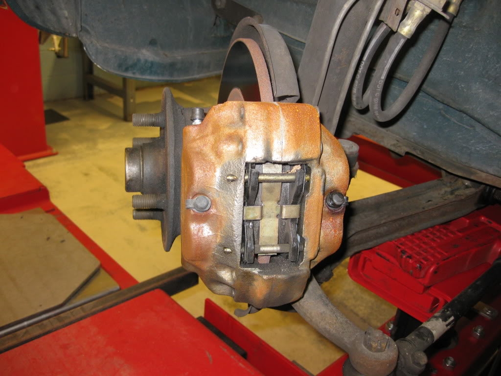 I went to install front brake pads on my '73 2002 with stock brakes earlier this week. My current pads ended up still having plenty of life, but I thought I would post pictures to the extent that might help others. My process followed from Haynes: 1. Parts/Tools - new brake pads, 1/8" flat head punch, small hammer, brake cleaner (note: depending on the condition of your retaining pins and anti-rattle spring, you could need replace them) 2. Jack up car and remove the front wheels 3. Extract the two retaining pins using your small hammer and 1/8 inch flat head punch to gently tap out the retaining pins and the anti-rattle spring. You tap on the small end of the pin located on the outer side of the caliper. See pic below of two pins and spring. Before picture of caliper, two retaining pins, and anti-rattle spring: 4. Withdraw the pads by gripping ends with a pair of pliers or using a flat head screw driver. In the picture below, I have removed the pins, spring, and the outer brake pad. 5. Once the pads are out, brush any dust from the ends of the pistons 6. Here is a picture of the pins, spring, and pads out of my car (you can also see the tool kit you'll need - mentioned in step 1). 7. Inspect the thickness of your disc pad friction material. If it has worn to 2.00 mm or less than the pads should be replaced on both front bakes as an axle set. My pads were okay. 8. Clean your pins, pads, and anti-rattle spring with brake cleaner. This is also a good time to check your rotors for runout/wobble, cracks, thickness, or other problems. 9. If you need to install new pads, use a syphoning device (I had a turkey baster - see below picture) to withdraw some fluid out of your reservoir. When you compress your pistons some additional brake fluid will be displaced and it will ensure your fluid reservoir doesn't overflow. If installing new pads, after removing the brake fluid from the reservoir (remember brake fluid eats paint and causes rust, so be careful with it), use a flat peice of wood or metal to compress the caliper pistons into their cylinders in order to accept the new thicker depth pads. 10. Install your new pads, the spring, and the pins in the reverse order. Here is what mine looked like after cleaning up the pins and springs. 11. After you put your wheels back on and lower your car to the ground... remember to pump your foot brake hard a few times, test your brakes, and top back up the fluid reservoir. You're done. -Marc4 points
 -
 Original Author: c.d.iesel After you remove all the SMOG krap , fit a new mechanical advance distributor, adjust valves, test compression, new plug wires, plugs, ignition timing set using a TIMING LIGHT , change all the fluids, wash and detail the car (that's good for a few more HP's!), and my WEBER 32/36 Jetting Prescription (actually over the counter and CHEEP!)your MPG and performance should improve. Please purchase ANY How To Tune WEBER carburetor book, many are found right on the Automotive selves of Barns & Noble , or other major book sellers. The WEBER Tuning book that Pierce Manifold offers is excellent. www.piercemanifolds.com ...my WEBER prescription: 32/36 Float Level 40mm PRIMARY idle 60 main 140 air correction 145 SECONDARY idle 55 main 170 air correction 175 AND -PLUG THE SECONDARY ENRICHMENT HOLE AT THE TOP OF THE CARB AS MY DIAGRAM SHOWS . DON'T ASK WHY- JUST DO IT AND SEE THE HUGE DIFFERANCE IN ACCURATE FUEL METERING THROUGH OUT ALL RPM AND THROTTLE OPENINGS.4 points


.jpeg.671912189ba2cf5f1c313cf74feb87e8.jpeg)


.jpeg.e8b71753a88f1ffaadc842a8c63b9fb8.jpeg)


.jpeg.e8a8c01f6f7c0e79a6dfeb756d739ff3.jpeg)


