


scanner
-
Posts
173 -
Joined
-
Last visited
-
Feedback
0%
Content Type
Profiles
Articles
BMW 2002 and BMW Neue Klasse Wheels
Colors
Steering Wheels
Production Years
Models
Registry
BMW 2002 Vendors and Shops
BMW 2002 Books
The Hack Mechanic
Forums
Blogs
Gallery
Events
Store
Books
Community Map
Videos Directory
Posts posted by scanner
-
-
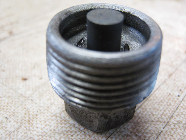
Please does anyone have any info about this part? I dont see any mention of it in posts but it is on BMWs EPC?
-
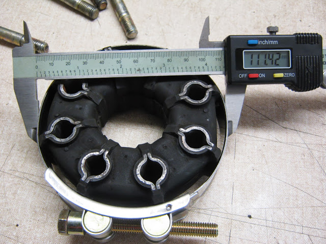
Ive just ordered this part from Walloth and Nesch http://www.wallothnesch.com/kardanwelle/bmw-1502-2002-turbo/katalogbild-26-05.html Part 26/05/01 but neither of my 2002s have it fitted. Is it because it had disintegrated or is it unnecessary? I assume it fits over the driveshaft and sits in the middle of the Guibo donut?
-
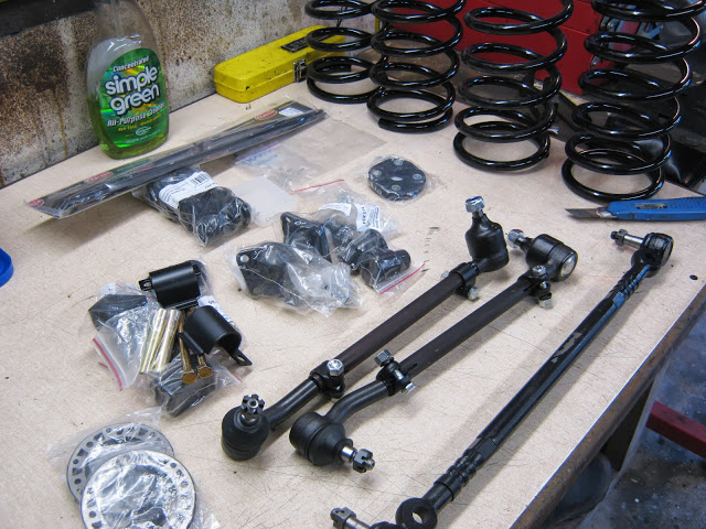
Small update, got back from the UK last week with a suitcase full (30kg) of parts - saved me a heap of money in shipping charges

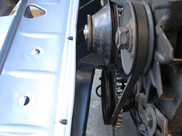
First thing to do was install the gearbox
Lubed the centering bearing on the driveshaft
and the pilot bearing
No photos of me getting under the gearbox and bench pressing it into position! In reallity it wasn't too bad, i used Mr Bill Williams trick of studs in the upper gearbox holes documented here http://www.bmw2002faq.com/_/technical-articles/engine-and-drivetrain/transmission-install-with-motor-in-the-car-r18 BTW i also gained all the bonus points!
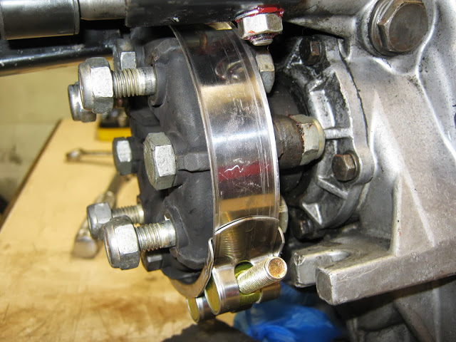
Guibo install - i admit to falling into a trap for young players here, i thought i would be clever and bolt the guibo to the gearbox while it was out of the car, it wasn't until i had installed gearbox i realised it wasn't possible to mount the driveshaft with the guibo on - it needs bolting to the propshaft first, then to the gearbox!
Original size of Guibo
Large hose clamp tightened up, bolts slid in easily after doing this
And mounted, unfortunately to be removed once i realised the propshaft issue!
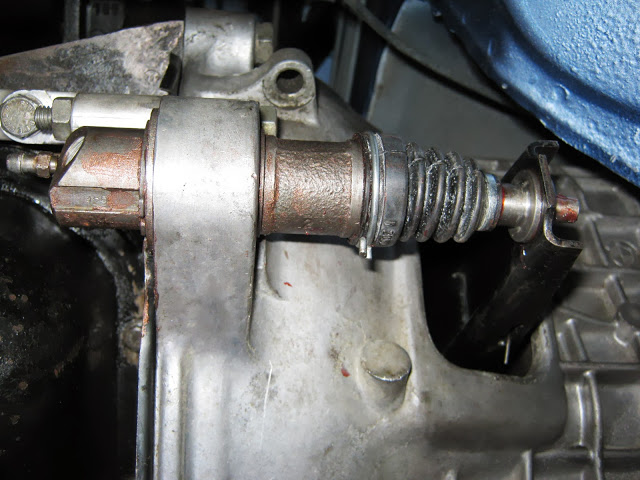
Clutch Slave cylinder mounted with new seals and plenty of Copperslip
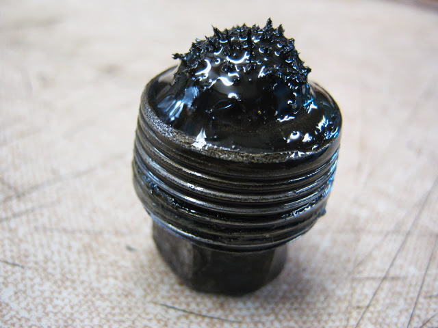
Gearbox drain plug removed, little concerned about the swarf but no large chunks so
Cleaned it up and
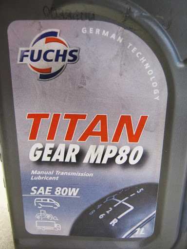
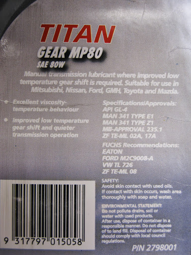
Filled it up - the label says 'German Technology' so it must be good!
Made sure it was GL4 spec
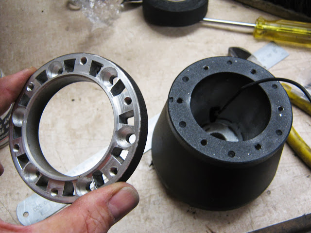
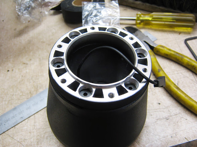
I also bought back a Momo Hub to Nardi wheel adapter
Now i can fit my nice Nardi wheel ive had for about 3 years!
Now i'm waiting on a small parcel of parts from Walloth and Nesch after which i will be planning on startup - yay!!
-
Floorpans are attached to framerails with spot welds, looking from inside the car you should see 2 lines of spotwelds for each framerail, attack these with a spotweld drill or angle grinder to seperate. Your framerails dont look good, lots of work involved there. You will learn heaps but it may be uneconomic to repair. Good luck and have fun!
-
I made up a metal bracket IMG_1533.JPG theres a few more photos n my blog dated 13th October http://www.bmw2002faq.com/topic/134019-73-fjord-with-megasquirt/ that may be helpful?
-
I did this a couple of weeks ago and can highly recommended the bread option, more effective and less messy than grease and alot cheaper than a puller. Dont expect to reuse the bearing though! Theres a post on May 5th about it in my blog http://www.bmw2002faq.com/topic/134019-73-fjord-with-megasquirt/
-
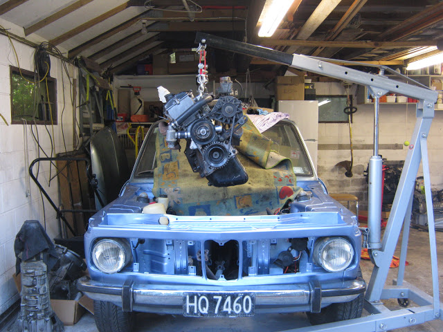
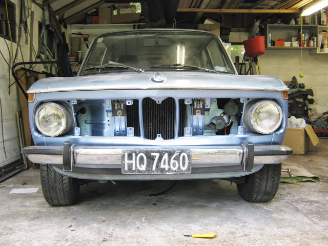
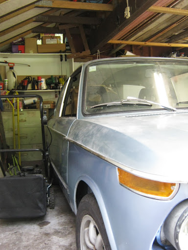
Engine In, Hood and Brakes
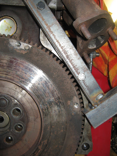
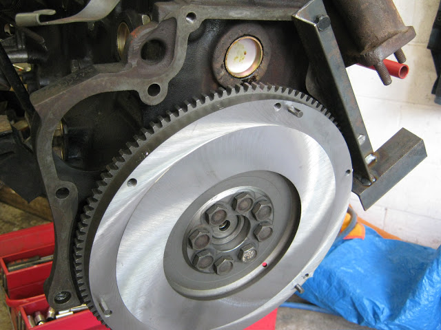
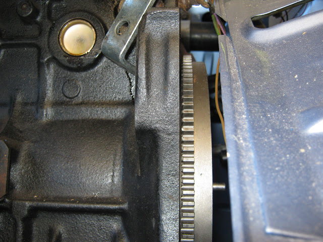
Homemade flywheel locking tool
Freshly machined - mmmm!
On its way back in
Tight fit but went in no problems, not necessary to tilt without gearbox
Back home!
Hood fitting as per FAQ.
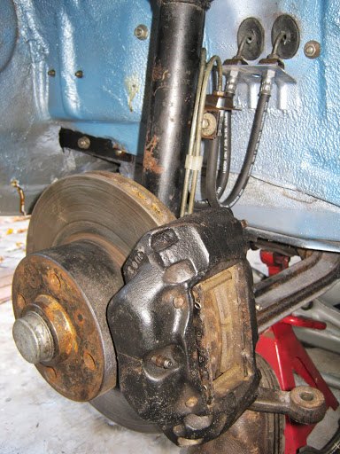
Volvo calipers with vented discs, as fitted by PO, refreshed with new flexible hoses
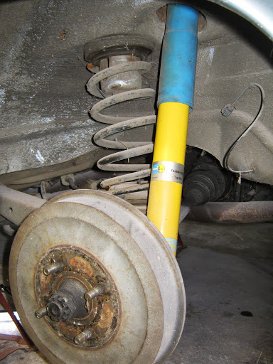
Bilstein Sports with 320i drums
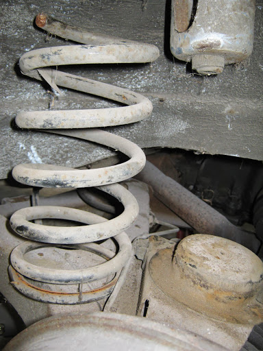
Rear springs have been cut and aren't captive, a big no no for passing a WOF in NZ, i will be replacing.
Brakes have also been bled, wiring tidied up in engine bay, all new hoses. Im taking a trip to the UK next week and hopefully pick up the final parts needed to get back on the road, hopefully just before blueys 40th birthday in September
-
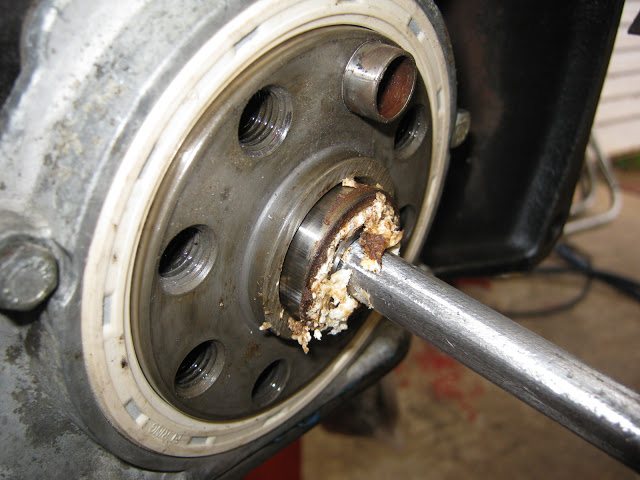
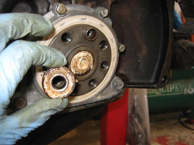
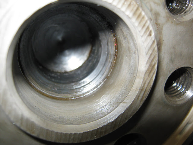
Pilot bearing removal using bread
This worked like a dream! I didnt have a suitable puller and had previously tried using grease which was both messy and unsuccessful! Came across this video so decided to give it a go.
Used a 12mm round bar to compress bread
2 slices is all it took
Even cleans up for you
The bearing was an open one and at first the bread squeezed through the gaps, but eventually it compacted enough and started to push the bearing out, wouldnt recommend trying to reuse the bearing though!
-
Seats and carpet have been refitted, i believe the front seats are from a Honda Integra, they fit without modification of the mounting points, so i can revert to factory seats easily. IMHO they dont look too out of place and are quite comfortable
Carpets a bit faded but servicable
Seats and Seatbelts in
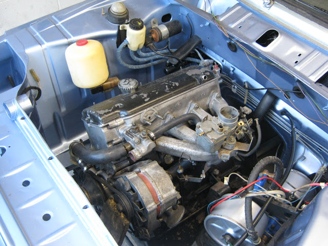
Engine reassembly continues, I ordered 2 permacoil kits from Amazon and they arrived within a week.
M6 fitted in timing case for water pump bolt
M8 for exhaust manifold stud
All frost plugs replaced, notice the evidence of a coolant leak, the original plug was almost rusted through. Loctite No3 aviation sealant used extensively on gaskets!
New water pump
New crank seal and gasket, Hylomar used on joint between seal housing and sump
Inlet manifold
and exhaust manifold, using copper coated nuts and lots of copperslip on the studs, installed.
Looks like the head has been milled approx 0.7mm, should give me a compression ratio of approx 9.1:1 which is fine, shame the upper timing cover hasn't been milled!. At the stage i dont want to pull the head off so will have to get creative with rocker cover sealing!
-
There doesn't appear to be a taper on my distributor so standard roll pin it is then - thanks guys
-
I have just had to assemble 1 good distributor out of 2 old ones, is it ok to use a standard roll pin (4 x 20mm) on the drive gear or do i need to flare out the pin or is it a special type of pin that BMW used?
-
More progress photos
Brake lines cleaned and reinstalled, brake/clutch reservoir added
Washer motor stripped down
Some serious oldschool over engineering here!
And installed on washer bottle, washer bottle leaked but managed to fix with careful use of a soldering iron to weld the plastic
Steering wheel installed, i have a genuine Nardi which will eventually be installed when i get the Momo to Nardi adapter.
Started stripping the ancillaries off the block, the plan is to leave the long block intact and check and replace gaskets ect as needed
Water pump had a broken stud, tried the welding a nut method - FAIL
So drilled out and collapsed thread
Stud screwed out -WIN!
Removed all core plugs
Glad i did, a couple looked close to failure
Removed Block drain plug to reveal?
What looked like solid metal, after chipping away turned out to be sludge build up.
A few more flushes of the water jacket should see it right.
-
Very cool video and looks like an awesome spot for a workshop - project is cool too - subscribed!
-
Satisfying to start to see parts going back in and the piles of cardboard boxes reducing
Pedal box fitted using 3M strip caulk
Brake and Clutch master cylinders refitted
Steering box in position
Rebuilt twin servos with new hydraulic seals, i have lots of photos of disassembly and rebuild and will post in the future (After road testing to confirm success!!)
Sorting out wiring spaghetti begins
Fused relays for Horn, Low beam, High beam and (in the future) Driving lights
Laying out wiring
Crimp tool and connectors used for relays, makes a nice tight crimp
First Servo added
Some wiring wrapped and second servo added
Next up - Brake lines
-
Now the engine bay is painted i can start reassembly, emptying some of the cardboard boxes stored around the garage.
Pedal Box (RHD) epoxy primed, fitting was straightfoward using 3M Strip Caulk
At this point i cavity waxed areas that were easier to get at before i put anything else in,
this is top of the plenum above where the heater box sits
Wiper arms needed a cleanup
New grommets fitted
Painted and greased up
And fitted, i fitted the wipers before the heater box to make life easier,
its a tight fit in there when the heater box is fitted
Heater box and valve refurbed, new hose and stainless hoseclips
And fitted, again using 3M Strip Caulk. Now the Heaterbox is fitted i can start the interior refit
In my latest package of goodies from Walloth and Nesch were the famous 'Corn Cobs" for the doorlocks.
Fitted one and it really does make a huge difference, door closes with a satisfying Clunk now!
The company i entrusted removal of the steering box arm to managed to feck up the alloy housing making oil seal replacement difficult!
Really pissed off but dont think the oilseal was too bad anyway, it was the other seal that was leaking
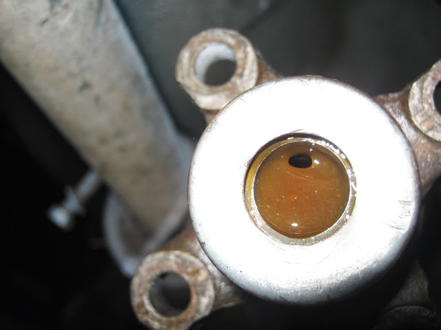
Ready to rebuild steering box, using EP140 (GL4) Oil to try to minimise leaking
Cleaned and ready to assemble
Job Done, filled with oil, will check tomorrow for leaks!
-
Reached an important stage in the refurb today - painting the engine bay. I went with an epoxy primer (already done) and a 2K 2 stage Basecoat/Clearcoat system. This is the first time i have used this paint system, all previous projects were with good old lacquer.
Masked up
First base coat on
Basecoat goes on flat.
I made the mistake of putting the first coat down too heavy and got a couple of runs, so i left it an hour and wet sanded the run with 600 grit and wax and grease remover, it worked perfectly. I wish i could take the credit but i You Tubed this very helpful 'How to" from a fellow Kiwi!
Basecoat finished, 3 coats and a final dropcoat, metallic looks pretty good, no 'tiger striping' fortunately
3 coats of clearcoat and the jobs done! Pretty happy with the result
Color variation
This has been the only downside to the process, the color doesnt match the bodywork! The paint i used was Spiers Hecker Permacron mixed to the Code and the color the body had been repainted by the PO is lighter than the factory color, hence the variation. Looks like a good excuse for a future respray!
-
The PO had put electric windows in which may have worked OK but im a great believer in the KISS principle and wanted to keep the electrics to a minimum. While dismantling the doors i discovered that both locks were non functional and some rust holes at the base of the door - project creep strikes again!
This wont be an extensive 'how to' as all i did was glean advice written by other forum members and in particular these 2 websites http://www.zeebuck.com/bimmers/tech/doorlocks/doorlocks.html and http://www.my2002tii.com/may2003/may2003.htm
So onto the photos!
Removed the electric windows, i believe from a Ford Mondeo
Rust at bottom of door cut out
Patches welded in
Bottom of doors epoxy primed, stone chip undersealed and wax treated on the inside, should keep the rust at bay for a while!
Door brake seems servicable
Standard problem here, will follow Bill Williams FAQ to sort this out
Regulator well greased up, hope i haven't overdone it?
Door lock soaked in petrol to clean off crud
Then blown with compressed air and Brakeclean, replaced grommets and sprayed with a PTFE lube
Assembled out of the car
And bolted in, (rubber grease used on the grommets)
And locks refurbed as described in the website mentioned above, i also reyeyed the drivers lock to match the ignition by filing down the tumblers.
And so to reassembling the windows, i was ready for a fight here but i think i got lucky and the order i put things back in seemed to work well so for what its worth heres how i did it!
Placed rear guide in but at this stage left it loose
After mocking up on the bench with the guides, removed the guides and dropped the window into the door
Quarterlight was already in the door, snapped the front guide into the front guide rail and bolted loosely to the window.
Bolted rear guide to window
Slid regulator in and attached to window, this took a few attempts to get the right window/regulator position to allow 'docking' to take place!
Regulator was bolted up (This was after mating it with the window which allowed me a little more wriggle room)
Rear guide rail was then moved forward and bolted loosely into position
After an hour or so of adjusments the window now moves up and down smoothly, more fine tuning will follow but still a satisfying outcome
Door trim still to put on, am waiting on the U channel felt strip to come from Germany
Well thats the passenger side done, will do some other stuff before tackling the drivers side, i need a break from wrestling with greasy regulators!
-
Thanks for the feedback. Looking to get the engine bay color coated this weekend, then can start putting bits back in!
-
More progress with the tidy up of the engine bay and underfloor
Welded up some of the POs mounting holes
And added a bracket for the Hella relays
Scrubbed the underside with Simple Green
Came up pretty good i think
Brushed on seam sealer over the epoxy primer
And sprayed on rubberised underseal using a schutz gun
Wheel wells done as well, i like the grey but may spray a light coat of fjord blue to look more 'factory'
Covers my welding repairs well!
This is the stuff i used, i think its German but available in NZ from R A Johnson, goes on nice and thick and is a pretty good match visually for the factory underseal.
Next on the to do list - rub down the existing primer ready for a coat of epoxy primer
Ready for epoxy primer
Although this is to be a daily driver the opportunity to spray a clear engine bay isnt one to be missed, so i am probably lavishing more attention on this stage than i will be on other parts of the build!
-
Finished the floor and firewall welding, as far as i can tell this is the worst of the rust and at this stage dont plan to look too hard for any more - this is going to be the daily driver so a little rust is acceptable!
Rotten metal cut away
Firewall patch formed
Took the opportunity to treat the insides of the chassis rails with Brunox rust treatment followed by a waxoil type treatment. Rails were in good condition with only surface rust on the inside
Extra plate added on the top of the rail to provide a solid base to weld the gas pedal locating nubs bracket to. Copper coloured paint is weld through primer
Final floor patch formed and holes drilled for plug welding
And welded in
Gas pedal bracket positioned and plug welded on
2 pack Epoxy primer brushed on
Seam sealed
Final coat of paint - Job done!
-
Finished testing the wiring, everything works, all relays and switches function. I had to take off the ignition switch as i was getting an unreliable contact in the 'fhart' position; 2 screws at the back and it comes off without taking the keyed part off, squirted some contact cleaner through it and greased the ball bearing and works perfect now. Sorry no pictures of this
Welded on a good solid earth that i can use a jump lead on - the battery has already been relocated in the trunk by the PO.
Added an earth strap and small earth distribution box from the Merc i took the loom from, giving me a convinient point to add additional earths for the megasquirt and additional relays
Earth in trunk cleaned, may swap screw for a bolt and nut for peace of mind
Earth on heater box bolt is good
This is where i can use jumper leads, positive power distribution box is from an E36 (couldnt find an E30 one!)
First sign of life! interior light. Basically i just went through each circuit, adding fuses, checking continuity and then powering up. By the end of the weekend everything worked
Found this little NZ Native when i took the back seat out, its a Weta, harmless and very cool - ill find a place for him!
I am missing one of these, its the parking light holder for an H4 Headlight, hopefully still available from BMW
Doesnt look much different but its alive now!
Instrument console cleaned and refitted
Loom under dash tidied up and rewrapped with bias tape
And onto the next project. Brake master cylinder refurb.
-
Sorry to keep on posting similar questions but i am slowly putting the pieces of information together before cutting!
My '73 (RHD Squarelight) has two fuses for the low beam (one for each side and a relay in the circuit before the fuses.) The 86 terminal is looped into the feed to one of the main beams. This appears to be correct to the factory wiring diagram and i have been told that this is so the low beam lamps turn off when Main beam is turned on
What i want to do is put in a mainbeam relay(s) to reduce the load on the lightswitch and stalk.
Should this relay be positioned before or after the loop to the low beam relay? My thought is that it should be between the fuse and the low beam relay because if i position it between the low beam relay and the main headlight it will be inturrupting the earthing of the low beam relay?
Im also thinking of having a separate relay for each high beam or is this just overkill and a waste of time?
-
Your correct, low beam is grounded by the highbeam.
Not sure why but it makes the the low go out when high is on. might be to save lamp and reflector due to heat.
I have mine rewired, one relay for low and one for high, high still feed ground to low beam relay.
Thanks for the replies guys, i kind of get it and if it works then why mess with it! What i do want to do is put a mainbeam relay in to reduce the load on the lightswitch and stalk.
Should this relay be positioned before or after the loop to the low beam relay? My thought is that it should be between the fuse and the low beam relay because if i position it between the low beam relay and the main headlight it will be inturrupting the earthing of the low beam relay? Or do i just not get it at all!!
Im also thinking of having a seperate relay for each high beam or is this just overkill and a waste of time?
All help gratefully received and appreciated
-
My '73 (RHD Squarelight) has two fuses for the low beam (one for each side_ and a relay in the circuit before the fuses. On the 86 terminal i would have expected there to be an earth but instead it seems to be looped into the feed to one of the main beams. This appears to be correct to the factory wiring diagram but seems strange, can anyone shed light on why it was done this way?
I was considering bypassing this loop, run the low beam relay terminal 86 straight to ground, then run a separate fused relay for each main beam connected after the fusebox, or is it overkill to have 2 main beam relays? BTW there is no relay for the mainbeams atm.


Cool Pic Of 2002S And Bmw 2000
in BMW 2002 and other '02
Posted
Love it, awesome artwork