


scanner
-
Posts
173 -
Joined
-
Last visited
-
Feedback
0%
Content Type
Profiles
Articles
BMW 2002 and BMW Neue Klasse Wheels
Colors
Steering Wheels
Production Years
Models
Registry
BMW 2002 Vendors and Shops
BMW 2002 Books
The Hack Mechanic
Forums
Blogs
Gallery
Events
Store
Books
Community Map
Videos Directory
Posts posted by scanner
-
-

Car needs work but the backdrops primo - Rangitoto, Auckland, NZ
-
 2
2
-
-
Great project thread. Personally i'd leave the cat hair on the cat and replace rusty holes with good steel or if extensive a rust cut of the tyre well, especiallly as you are doing such a thorough job of the rest of the car. Keep up the good work
-
Hi, Jaymic do headers for RHD cars
http://www.jaymic.com/shop/parts_02_products.asp?grp=02EX&page=6
No idea how good they are but may be worth investigating? Seems expensive though, maybe getting a set made here could work out better? Sorry cant help with finding power - i doubt if mine is making more than 70hp at the moment ! Going with the webers must be tempting to be able to compete in a more appropriate class though. Cheers Chris
-
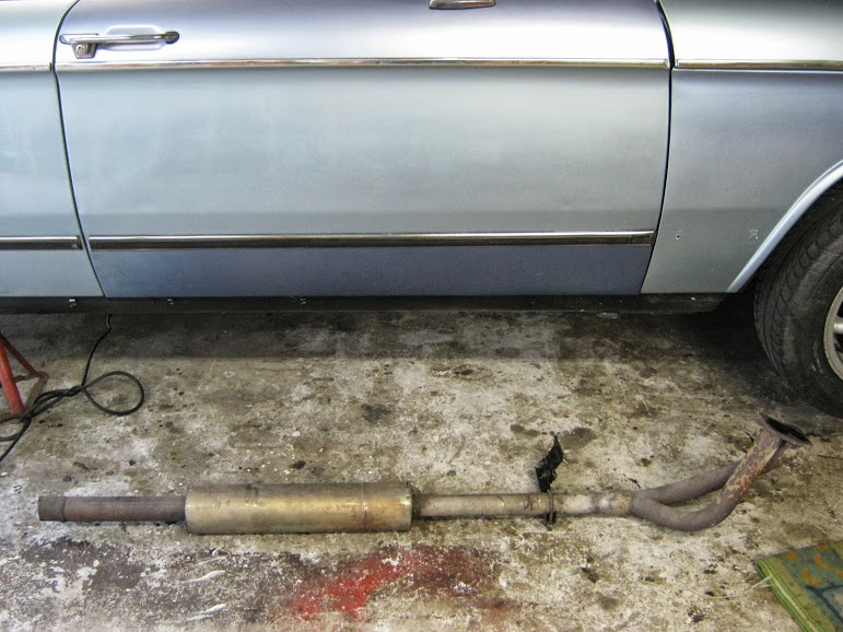
The muffler had developed a rattle, the center core with the holes in it had come adrift, instead of replacing it i decided to run without a front muffler.
Pipe cut at rear and separated from manifold at the front, pipe was 46mm entering the muffler and 51mm leaving
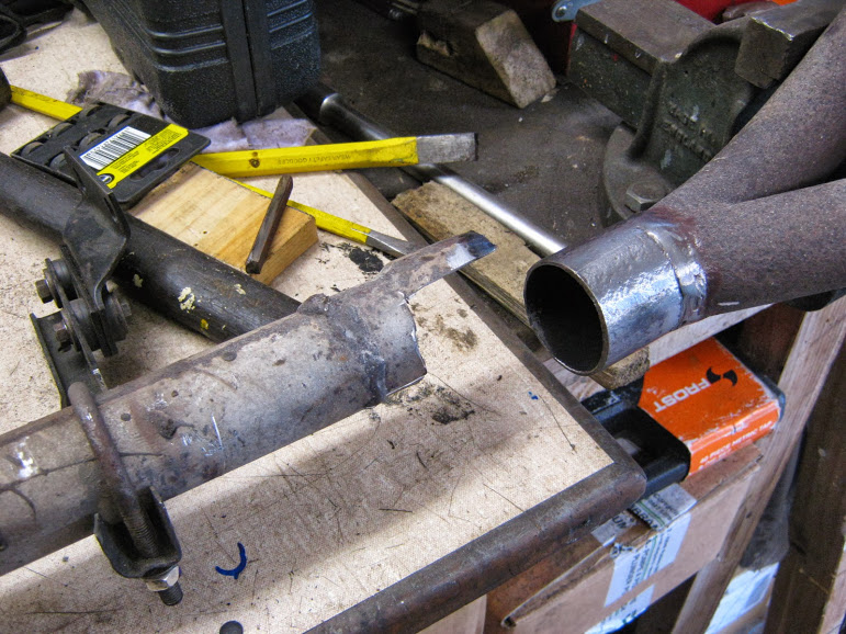
Old pipe carefully cut away from the downpipe.
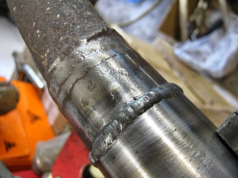
300mm of 51mm (2") pipe welded onto the downpipe.
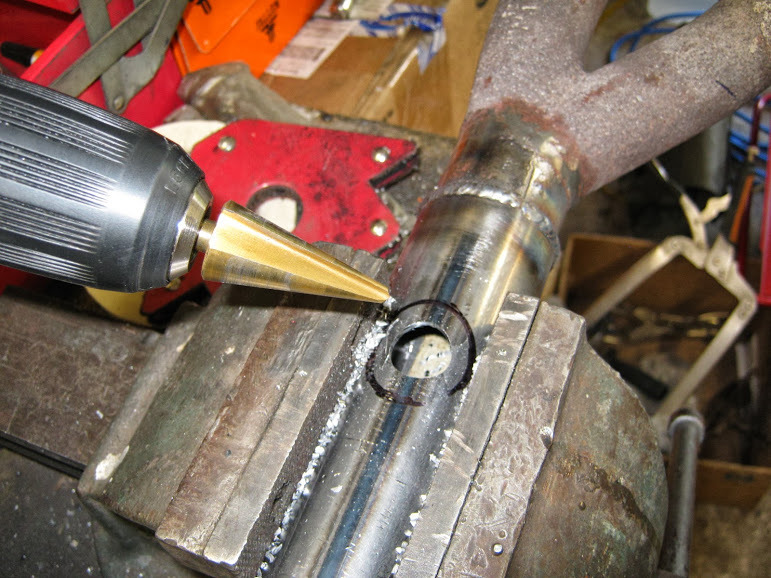
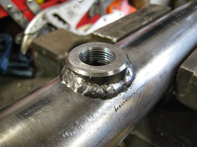
After mocking up on the car i drilled a hole for a oxy sensor, there is space between the gearbox and tunnel to put the sensor in at 12 o'clock
And bung welded in
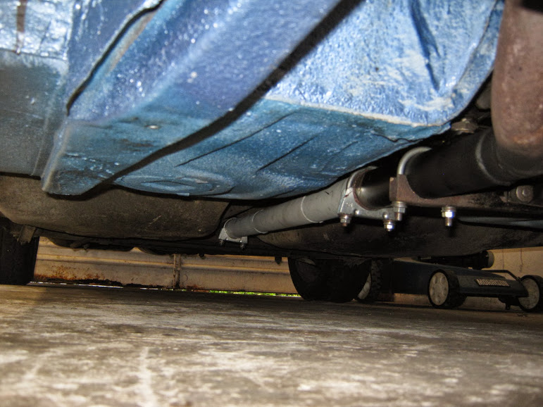
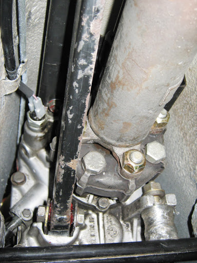
Downpipe mounted securely, the gearbox support bracket needed to be opened up to fit the 51mm pipe snugly. Then added a length of 51mm pipe flared at both ends and secured with exhaust brackets.
The straight pipe needed a couple of kinks in it to get it to marry up with the rear section smoothly, but after a couple of attempts managed to position everything so it didnt hit diff housing/CV inner joint/ rear subframe!
After driving for a couple of days, i think i will add a resonator at some point, its not unduly loud but it has a rasp to it that to be sounds a bit 'ricey"!! I prefer a burble to a rasp
.I have also finally made a start on the Megasquirt side of things - i have felt a bit of a fraud about the "with megasquirt" part of the blog title so to put things right
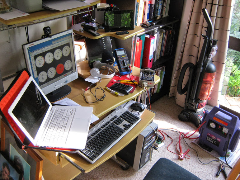
The test bed! No laptop but the old PC had a serial port so i loaded Tuner Studio and set up the relay board and Megasquirt, it powered up OK and after a couple of false starts managed to get the latest firmware loaded on the MS and Tuner Studio to talk to MS.
The plan is to get the ignition side working first as I have all the components (EDIS), and i think i will see a good improvement to performance with a good advance curve and crank controlled timing instead of my worn distributor, dodgy advance springs and.rattly timing chain. I do love the simplicity of points but the benefits of this ignition alternative are too compelling to ignore - time will tell ( and i can always go back to points if modern technology gets the better of me
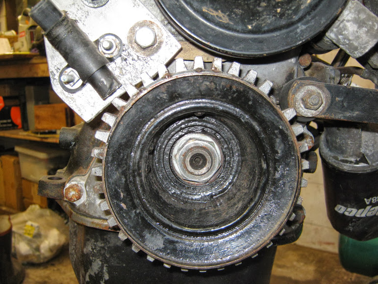
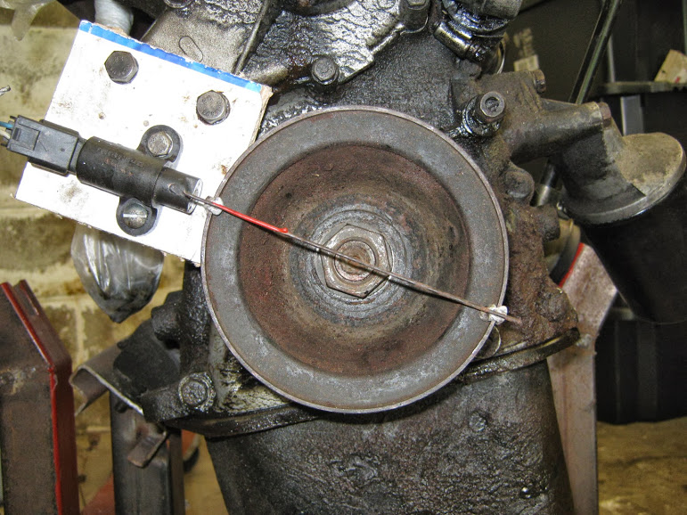
)Heres the 36 tooth wheel as mounted at present. Unfortunately the wheel is not mounted in the correct place to take advantage of the 10 degree BTDC 'limp home' mode that edis offers should the Megasquirt fail. At the stage i am thinking of repositioning the wheel on the pulley.
Before i pull the pulley off i thought i would use my spare engine to mockup a new VR sensor mount, if i position the missing tooth 1 tooth BTDC then 90 degrees before that is where the VR sensor can be placed without fouling on the water pump bolt - its my understanding that as long as the engine is at TDC i can mount the toothed wheel anywhere, as long as the VR sensor is 90 degrees behind it?
-
Well its been a month, no major problems but had a couple of leaks that needed sorting -
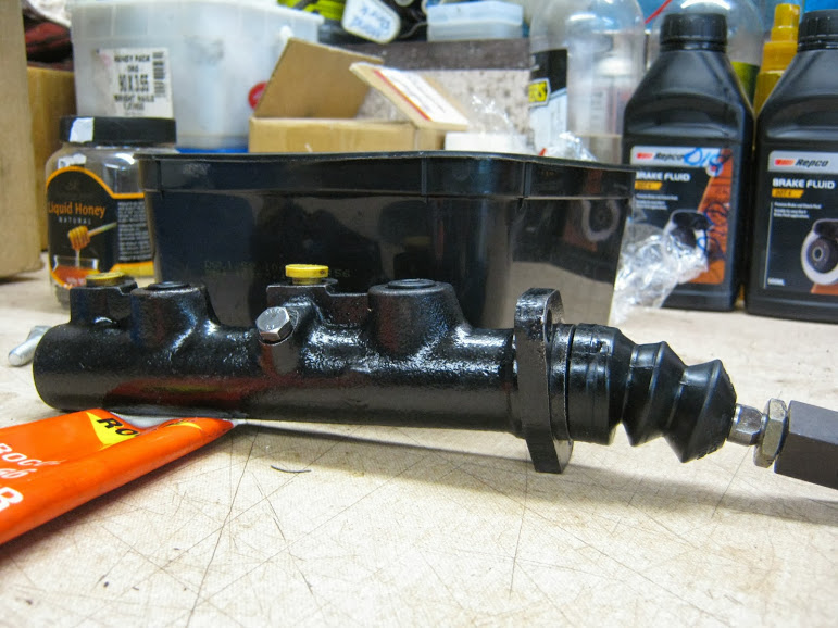
Brake MC leaked from day 1, took it to Just Brakes in Auckland (highly recommended) expecting it to need sleeving, good news was the bore was in excellent condition, just needed a light parallel hone and a new seal kit. I was expecting the bleeding to be a PITA but turned out to be easy, all the air bubbled out of the remote reservior with some light pumping of the pedal!
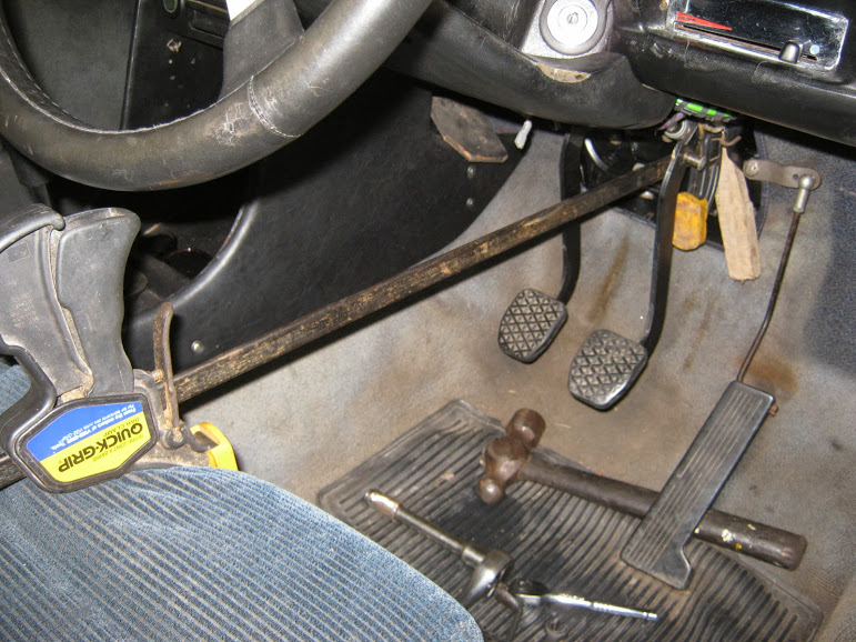
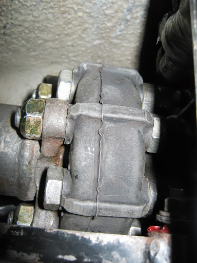
Used this clamp to keep MC bolts in while i put the nuts on - have to be creative when theres no one around!
Job was made so much easier with the engine bay clean and having only put it all together a few of months ago - didn't even spill any brake fluid!
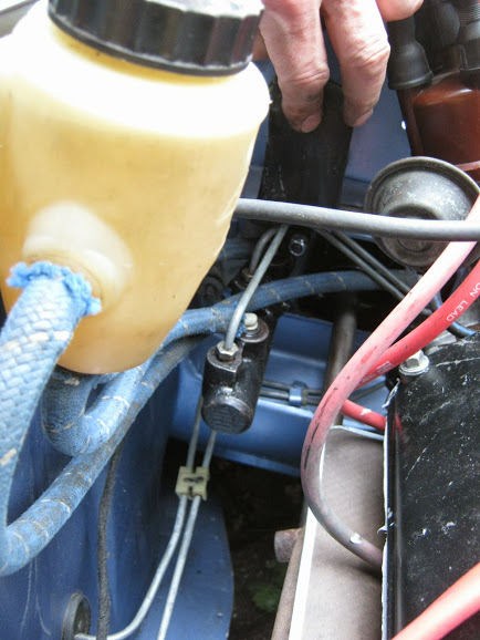
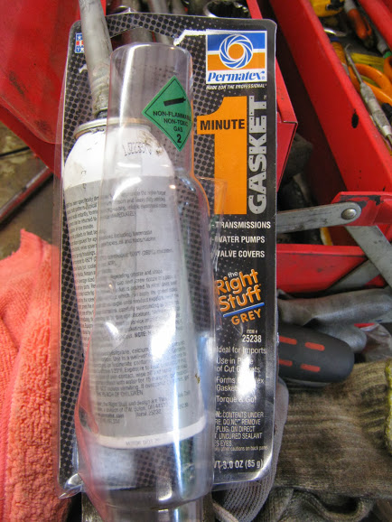
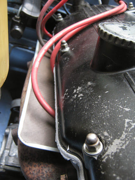
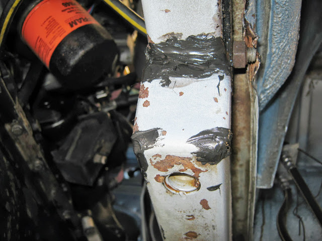
The second leak was the rocker cover, because previously the head had been skimmed but not the upper timing cover there was a .70mm gap between head and rocker cover, not good. Not wanting to remove timing cover at this stage i thought i would try this stuff
Put .70mm washers under the studs on the head only and added gasket goo
Result - Ugly but effective, been for a few runs and so far no rocker cover leaks
Also started trying to get a bit of shine on the paint, used a claybar, meguires polish and then carnuba wax
1/2 done -They say you cant polish a turd but ill give it a go!
-
Im about to start a similar megasquirt project with the relay board and i was wonderingh ow are you powering the EDIS? I was thinking of using 2 of the 4 power takeoffs to run the injectors and 1 to power the EDIS leaving 1 spare?
-
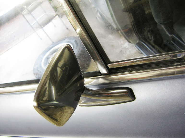
I used the 3M Caulk strip, seems ideal for the application, just the right amount of pliability to conform to irregularities and tackiness to stick to paint and plastic
-
Check out Walloth and Nesch, they sell the sill and a repair panel for the lower rear quarter (which you will have to cut out to repair the sill properly)
-
Try checking your grounding points and straps are clean, metal to metal contact (Battery to Body and Engine to Body)
-
Back on the road!
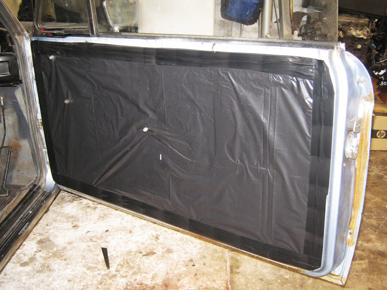
Final push to get legal, finished off the doors
Black bin liner did the trick!
Mirrors fitted
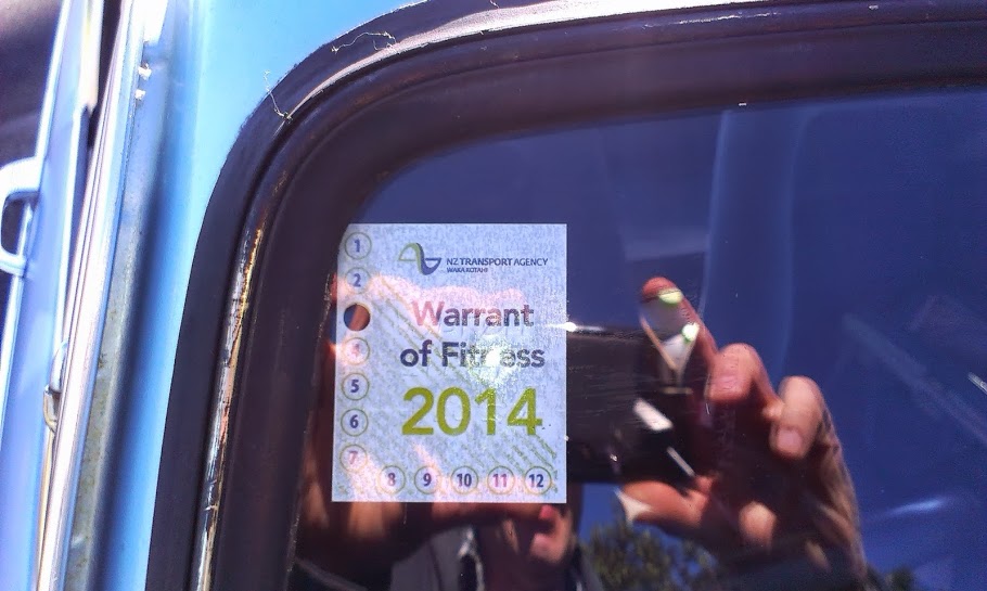
Not many photos taken, i basically spent a couple of weeks sorting out teething problems, some self inflicted - dont forget to do up wheel nuts before going for a test drive is one tip! I also reset timing with a strobe, set toe in using this method http://www.bmw2002faq.com/topic/116459-diy-alignment/ (worked really well BTW). Swapped leaking radiator for the spare fortunately non leaking one, rebled back brakes. Finally last friday i took the plunge and went for a Warrent of Fitness (WOF). It failed - but only for a bad wiper blade and badly aligned headlights!
So yesterday i went for the retest and
WOF
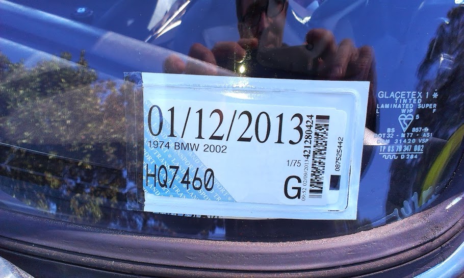
And vehicle license
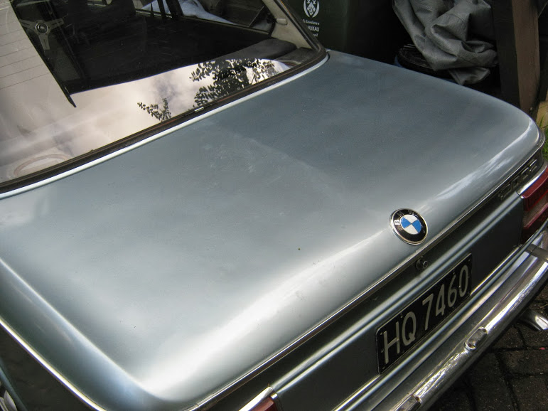
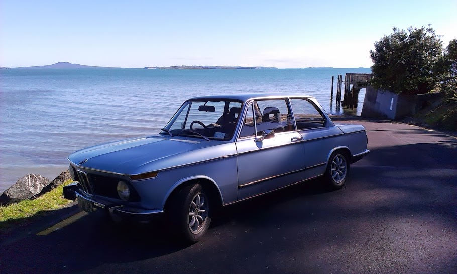
Fully road legal -Yehaa, it was also a beautiful spring day in Auckland so took a few glamour shots at the local beach
Very happy with the outcome, this is the first 2002 i've driven and im not dissapointed. Engine is nice and torquey, pulls well from low RPM, suspension is compliant and feels great around the twisty bits, brakes are good, steering is pretty good, quite heavy but i have wide tyres on so only have myself to blame! The plan now is to just use it for a few months and enjoy
-
"Tell him he's dreaming" - (quote from classic Aussie movie 'The Castle')
-
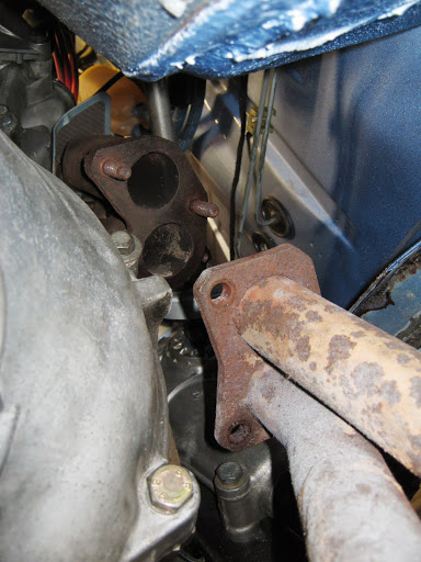
On mine (RHD) it's a guide for the manual choke cable.
-
Sorry - posted in wrong topic!
-
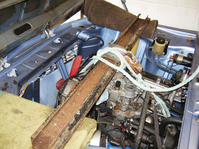
Its been a frustrating but ultimately satisfying couple of weeks, i was preparing for first startup and first i spun the motor without plugs to get oil pressure. After trying various fixes and picking forum members brains http://www.bmw2002faq.com/topic/142902-oil-pressure-setback/#entry936750 i dropped the sump
Engine supported from above
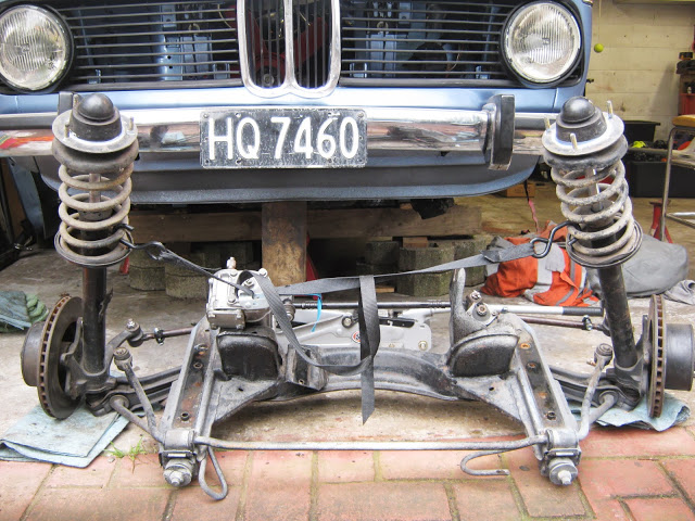
Subframe out
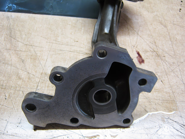
Oil pump removed, cleaned and measured - checked out ok
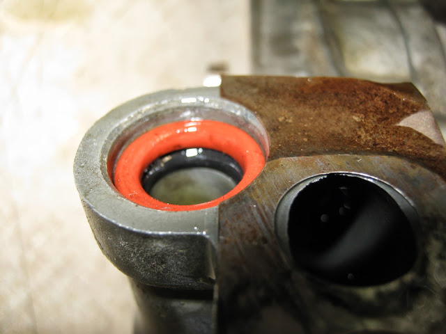
As discussed in above post, 2 O rings added which sealed nicely
If this was a rebuilt engine with lots of $ spent on it i would not have done. But given it was an old engine, the oil pump checked out fine and if there was any damage due to low oil pressure it would have already been done i opted for the simplest solution. A new sump gasket from BMW NZ and engine was back together. After cranking for about 20 seconds i got a good flow of oil out of the sender gauge hole - success!!
With the subframe out i took the opportunity to replace strut ball joints, tie bar front rubbers, sway bar rubbers and replace cut springs with Jaymic 30mm lowered springs. I wont document subframe reconditioning as it has been done by others far better than i could, couple of photos though
Standard rubbers went in easy with the recommended insertion tool!
Silicon on frame ends to stop water entering here, i also took the opportunity to paint the rails with the subframe off
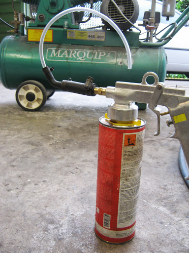
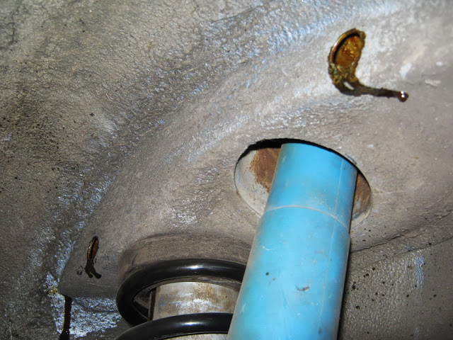
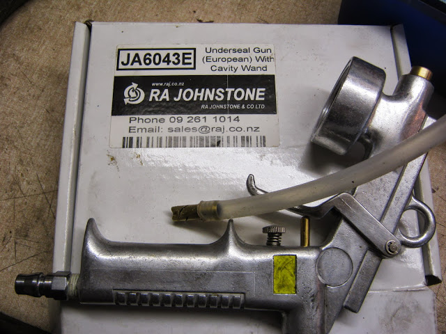
Modified cavity wax gun to get in the frame rails via the subframe bolt holes.
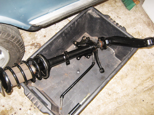
Built up the struts, ball joint and control arm off the car to make access to nuts and lockwiring easier.
No photos but i attached the steering and idler (RHD) box and the sway bar to the subframe, then offered the subframe up to the frame rails, this allowed me to keep the subframe as light as possible to allow easy bolting up to the engine mounts and frame rails. I then added the tie rods and finally attached the struts/control arms as a unit. This all bolted together really easily and i would use this method again
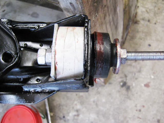
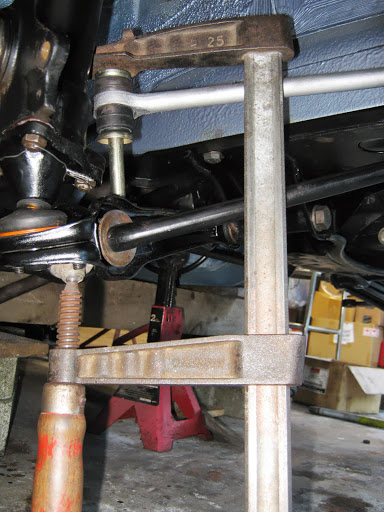
I was struggling with the swaybar rubbers until i used a C Clamp positioned like this and it all went together easily.
Job nearly done, the control arm to subframe mounting needed torquing to 123ft/lbs almost impossible to do with the car on the ground with lowered suspension so instead i put a jack under the strut and raised the strut until it was just taking the weight of the car and then torqued up - good enough i hope to avoid strain on the control arm rubbers - sorry no photos
And so to today, new fuel in tank, plugs gapped and timing set roughly using a test lamp, full choke and ........... STARTED FIRST KICK!!! Really happy, ran for a 5 minutes, turned off and checked for leaks and fluid levels. I then tested clutch and gearbox and drove out the garage, cue compulsory startup video -
At the end of the video you will see that the fuel pump is leaking, luckily i had a spare which i swapped over and fortunately worked perfectly - you have to catch a break sometimes!
To end a successful day i even treated bluey to a wash
-
1
-
-
Thanks Toby, yep i think it may be a mix and match engine, its a 1974 car (matching numbers) but its the old style pump, at what date did the change to the new pump take place? Anyway, i will try to sort out an oil pressure gauge for peace of mind.
-
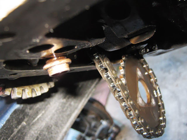
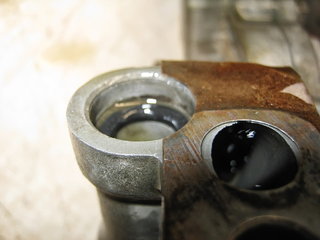
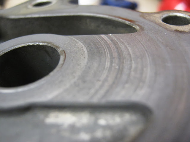
Update - Put pump back together, no obvious issues, when i went to fit the pump to the block i noticed this -
Flange that O ring sits against is approx 4mm below the pump mounting face
O Ring sits approx 6mm down the housing, so wont contact flange and create seal
The solution - add a second O ring, when i offered the pump up to the block i could now feel the O ring compress slightly as i pushed the pump home.
I then temporarily put the sump back on, filled with oil and cranked on and off for a good 2 minutes, removed the oil sender, cranked some more and then suddenly turned from a drip coming out to a solid gush - not shooting in the air but a decent flow. I then replaced the sender unit, cranked and the oil pressure light went out almost immediately
My concern now - is the 2 O Ring solution ok or a disaster waiting to happen, bear i mind this is an old engine and i suspect the damage due to weak oil pressure may have been done when last run by PO and i dont really want to remove timing covers because that will invariably lead to project creep which i cant afford at this stage.
I also tried to take a video of the oil coming out the spray bar - its not really spraying though - is that because its at cranking speed or do i still have a problem, you can just make out the oilflow towards the end of the clip
https://picasaweb.google.com/105528953083937093443/July252013_OilPump2#5904423591993993442
-
Thanks for all the replies guys, the relief piston was free in the bore and moved up and down smoothly, spring was correct (68mm) length. Gear surfaces looked good and measured to spec, no obvious blockages noticed and the pickup wasn't damaged so atm the mystery remains. I plan today to pull the oil pump from my other motor, compare and choose the best one, bolt it back in, temporarily bolt sump back on crank it and see how much oil spurts out the filter housing - not very tech but hopefully will reveal an improvement? Ill also blow through the block oilways with compressed air before putting the pump back on. Fingers crossed!
-
The method outlined in post #11 here http://www.bmw2002faq.com/topic/134019-73-fjord-with-megasquirt/?p=18322 worked for me. I think a bit of hand tearing is compulsory though
-
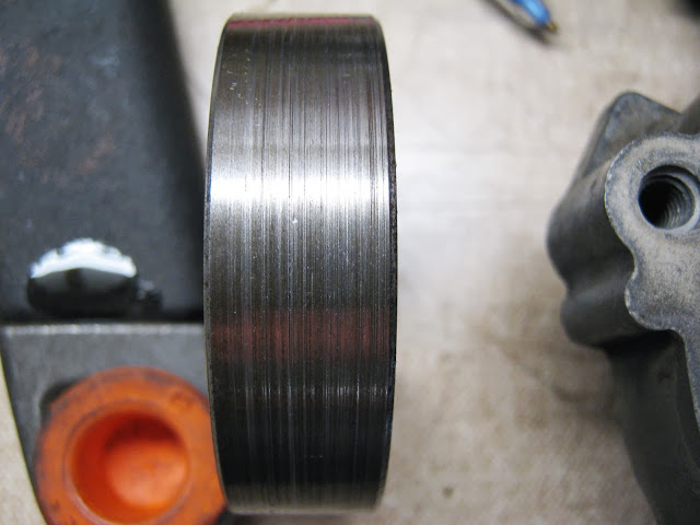
Subframe dropped and pump removed, measuring with feeler gauges showed clearances were within spec but there is some wear and tear -
Outside of outer rotor
Face of housing cover
Is it usable in this condition and is it possible to flatten the face of the housing cover by rubbing it on wet and dry paper on glass?
-
suspect o-rings at location #20 fubar :
Will check and replace these for sure, im wondering that maybe the mesh prestrainer is blocked up with crud, restricting flow? All will be revealed this week hopefully!
-
Thanks for the replies guys, good news about the bearings, but as Toby commented the oil flow rate doesn't seem anywhere near adequate. I think the plan will be to drop the front subframe and sump, remove and check oil pump and while the subframe is out do a refurb with new rubbers, something i was hoping to do in a few months but may as well do it now.
-
My project had been going well http://www.bmw2002faq.com/topic/134019-73-fjord-with-megasquirt/page-2
but today i hit a major setback. I cranked the engine over with no plugs in, after a few 15 seconds bursts the oil pressure warning light was still on so after searching the forums i
i) Removed the oil sender unit and cranked the motor for 20 seconds - no oil spurting out.
ii) Ran oil down the oil sender hole, cranked, ran more oil, repeated 4 or 5 times - still no oil.
iii) Removed oil filter (that i had previously filled with oil) it was empty, i then cranked the engine for 20 seconds and only 150ml of oil came out, repeated this 6 times each time with the same result, oil came out but not alot.
At this stage i tidied the garage, walked away and pondered the next step which is probably to drop the subframe, sump and remove and inspect oilpump. Before i do i thought i would ask
a) Is 450ml of oil per minute less than it should be?(Im guessing it is)
b )Is there anything else i can do before disassembling?
c) Will i have damaged bearing shells by cranking probably about 5 minutes in total with no plugs in ( its not a newly rebuilt motor, has plenty of miles on it already
Sorry about the long winded post but trying to give the full story!
Cheers Chris
-
Old record 9.46 new record 8.13? That seems unbelievable even for the greatest WRC driver ever, has the course changed or is Seb really superhuman?! (I think he might me)
-
Package arrived from Walloth and Nesch so work continues
Guibo fitted with new retaining nuts
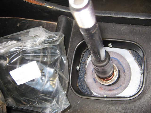
Remote adjusted, with new foam to keep dust out, new rubber gaiter in plastic bag to be fitted
All installed, should have used a 320i gearbox rubber mount but didnt know about that upgrade when i bought it so meh, next time!
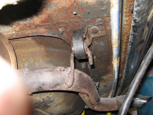
Refitted exhaust, new gasket nuts and lots of copperslip here
And new hangers
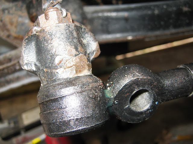
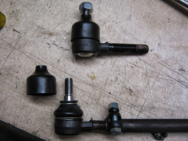
New drag link installed, no felt washer to soak in oil? Just a plastic cap
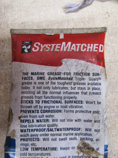
That i filled with this grease - have used before and its really good stuff, hope it does the trick.
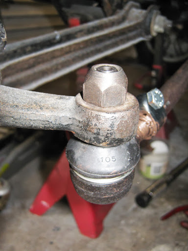
New tie rods, copperslip on adjusting rods. Notice protective plastic cap that covers the ball joint rubber, easy to leave on if you dont realise, luckily i had read a few posts of people who had done it so i was forewarned!
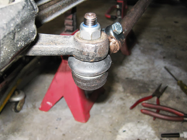
First put on tie rod end with non nyloc nut so the taper bit and the ball joint wouldn't rotate ( i used a wheelnut )
Then removed and replaced with nyloc torqued to spec.
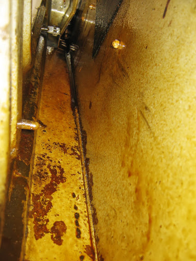
I then moved on to do some rustproofing with cavity wax
Sprayed the inside of the drivers door
And (after removing dry dirt with compressed air) the shock tower cavity
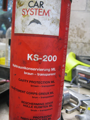
This is the product i use, creeps well and doesnt harden
Applied using this applicator
Startup getting closer!!


 )
)


73 Fjord with Megasquirt
in Project Blogs - Archive
Posted
EDIS Installation
First decision was where to mount the EDIS hardware, decided on these spots
EDIS Controller close to the VR sensor to avoid too long a cable length - it seems from reading the Megasquirt forums that one of the major causes of problems was poor signals from the VR Sensor and i wanted to minimise signal interferance. Position was also well away from other causes of electrical noise.
EDIS coilpack mounted (rather crudely but solidly) in position and using existing holes for the origional canister coil. This also allowed me to use the EDIS coil leads without modification, the lengths were perfect!
Also decided to mount the Megasquirt Relay box at this Stage - the block of wood will be replaced with a block of rubber at a later stage with the intention of isolating vibration as much as possible.
I also ran a separate 8 gauge wire from the battery in the trunk to the distibution box and then on to the relay box to try to minimise voltage drops when cranking. Switched power to activate the main power relay on the MS relay board was taken from Fuse 12 on the fusebox as it was 'hot' in run and when cranking. Ground from the relay board was to the engine and were the edis ground and shielded cable ground, all to the same point.
Crank pulley removed from engine - no puller available but with some blocks of wood and wedges got it off with no damage. Tack welds on toothed wheel ground off and wheel removed
After locating TDC using the flywheel OT line and mounting VR sensor i moved the toothed wheel around until the 9th tooth before the missing tooth lined up with the VR sensor, held it in place with hot glue and tack welded twice to secure. It then took a couple more attempts to centre the wheel on the crank pulley which i did by nearly grinding through the welds and tapping the wheel with a FBH then rewelding - got it on the third attempt! Access to a lathe would have been ideal to centre up but this did the trick. Put about 12 tack welds around the pulley to secure. At this stage i have aimed for a 1mm gap from wheel to VR sensor.
All that remained was to wire up as this diagram (EDIS 4)
Well not exactly as my EDIS controller had no pin 7 so i ran the sheilded cable from the VR sensor through the PIP/SAW sheilded cable to ground at the same point on the block as the MS Relay board and the EDIS Ground. I also left the PIP and SAW disconnected to test the EDIS alone in limp home mode.
At each stage of wiring i checked for continuity and then for voltage where appropriate.
I then connected one coil lead and spare plug and cranked motor - success - we have a spark!
Put back fanbelt and radiator connected up all HT leads and cranked, and cranked and cranked - nothing. A little disheartened i pulled a plug and noticed it was dry? Removed air cleaner and then noticed the fuel line had come adrift from the inline filter!
Reconnected fuel line, primed solex float bowl, turned up idle speed screw 1 turn and cranked, motor fired up 1st kick and after checking with timing light i have a rock solid 10 degree BTDC advance, exactly what it should be for EDIS running on its own in limp home mode - awesome!!
I realise i still have a long way to go but this was really encouraging, the timing mark didnt move around at all, with the admitidly old and worn distributor the timing mark used to jump all over the place, now i have a stable starting point for building the Megasquirt advance curve
Next step - connecting up the Megasquirt in car and building an advance curve