
This upgrade is to compliment a pre-existing Volvo/320i vented system (-or whatever it is you Tii fellas do..) that can be added to the front with relative ease.
In an effort to replicate the placement of the calipers in a rear conversion at the stock(ish) 3 and 9 O'clock positions as compared to the front calipers, I worked with Todd21 who had formulated a plan based on the work of others, combined with his own ideas.[/b][/b]
Here is the stock location of the front calipers which we are attempting ot replicate:

His concern, which as it worked out was OUR concern, is that the calipers in other designs were hung off the bottom, necessitating that the calipers be removed in order to get the bleeder vertical when... bleeding.
For example:

This led to a rather gutsy design and ultimately a fine product. Although the final products for Todd an I are slightly different, I will cover the reasons. The biggest being that we live four hours apart, and once I returned home and discovered the need to a rethink, reworking from afar was impossible.. so it evolved.
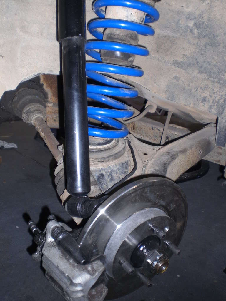
OK, so, for reference, here is a bone stock swing arm and bone stock assembly..


As you may have guessed, the stopper in anyone's design looking to get the caliper in the correct position, is the location of the rear shock boss. In this design, the stock shock boss is removed and thus relocated. (This is the gutsy part!!)
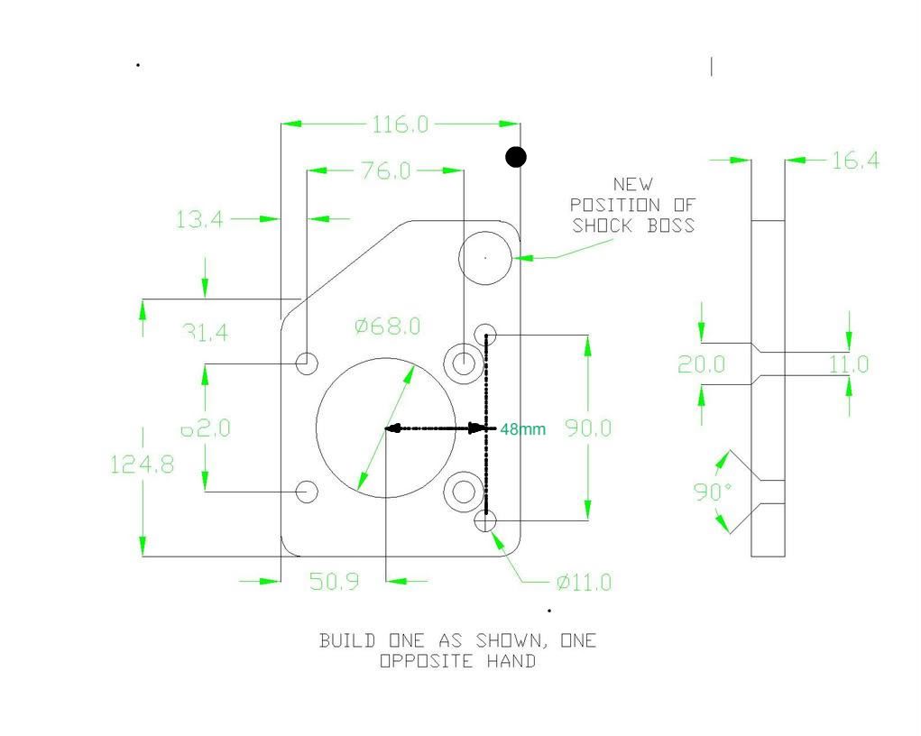
Here is the drawing for the adaptor plate, indicating the placement of the new shock boss.
This exact design worked well on Todd's car, with I.E. Stage II 235 LB. springs, 15X7 et 25 wheels and stock shocks. Where my Eibach progressive springs, 15X7 e25 wheels combined with Bilstein Sports (larger body to the shock), required a different shock boss location to provide clearance for the shock body and inner lip of the rim. As well, the lower shock boss location in my final offered more travel to prevent shock bottoming.. even with sports. The reason being, while Bilstein's have more aggressive dampening rates, they also have longer compressed length than the OEM shocks.
Todd's final:

My final:


As you can see, my design became a two part plan..

I was able to get the mounting location in an almost identical parallel to the original boss location. This totally eliminated the issue I was having with bottoming.
In hindsight, I will say that had I the ability to redesign based on the original drawing, I could have extended the shock boss to get the wheel clearance and the drop needed to have it all come together with just the plate. So going forward, I recommend this be the route anyone following this method use.
Once again, refer to Todd's original drawing, and extend the boss (test fit the plate with the shock and wheel installed to measure the appropriate boss dimension). See the next pic for a visual...

So without further ado, lets dig in to this..
Here is the parts list:
Donor car info:
· Rabbit Mk1 (A1/Typ 17, 1974-1984)
· Golf Mk2 (A2/Typ 19E, 1985-1992)
· Golf Mk4 (A4/Typ 1J, 1998-Present)
Parts needed:
QTY Description
2) VW Calipers (rear) from MK4, 2000 to 2006 Golf, Beetle, or Jetta (with lines)
2) VW Carrier Brackets (rear) from MK2, 1985 to 1989 Golf or Jetta
2) VW Rotors (front) from MK1 (74-84 Rabbit) (239x12mm)
2) Reduced OD hubs from 2002 (existing hubs can be modified at a shop, or on the car if you're clever..)
2) Adapter plates (see drawing)
6) M10x25 Socket Head Cap Screw
2) M10x20 Flat Head Cap Screw
1) Proportioning valve for rear brakes
1) 3’ section of 3/16” steel brake line
Procedure:
Start by jacking the rear of the car and placing jack stands under it to allow for safe work. This should be done on a flat hard surface it at all possible. All typical safety precautions should be taken to prevent the car from falling during the conversion. Very little, if any work will require getting under the car, but always err on the safe side. While we love our cars they can be replaced, we cannot.

Remove the rear wheels, brake drums, and hubs exposing the brake shoe assembly. The components of the rear drum brake assembly will be completely removed, including the backing plate attached to the spindle tube flange. The cable for the parking brake can be left hanging loose. The hard brake line can be removed back to the connection with the flex line at the trailing arm.


Remove the shock absorber mounting nut and slide the shock absorber off the trailing arm mount. Using a grinder or port-a-band saw cut the shock absorber mount off the flange. This is required to allow clearance for the caliper piston. The flange can be relieved as required during final fit to minimize the amount of the flange removed.


Install the fabricated adapter plates (see drawing) to the spindle tube flange using two socket head cap screws (SHCS) in the front holes and two flat head socket cap screws (FHCS) in the rear holes. The FHCS are required to allow clearance for the carrier bracket. Loc-tite 242 (blue) should be applied to all fasteners. Here we are test fitting with an early prototype bracket..


The rear hubs will be reduced on the outside diameter to allow the brake disk to pass over it. Take a measurement of the inside diameter of the brake disk “top hat” and then turn down the outside of the hub to allow the two parts to mate. Once the hub and disk is installed, test fit the carrier bracket and caliper to insure proper fit. The carrier bracket may require the slot for the disk to be opened depending on the location of the disk and hub.

Once the hub and disk are installed and the carrier bracket and caliper are installed, you will then install the wheel and put the swing arm under load with a floor jack. Do this to gather your measurements for the length of the shock boss. Check for clearance at the inner wheel lip, the caliper and the spring. You can reuse the original knurled shock mounting stud in your design. We used rod stock. Counterbored to accept the stud, and tack welded it into place.
Then.... here's the tricky part, Todd ground the boss to a 21 degree angle on the bolt head end. His best attempts at getting measurements on the boss orientation put it at 21 degrees down from the horizontal and rotated around 11 degrees to get the proper position. Just put the bolt/boss in the bottom mount of the shock and take a look. If it doesn't look right grind the angle to suit you and then put in back in the shock and see if it looks correct.
Once the angles and clearances add up, tack it into place , remove the plate and fully weld. (The position on the drawing is for reference.)
Next, the brake line from the VW are of very good quality, and can be installed on the trialing arm. Straighten out the hard line to allow for it to be routed along the trailing arm similar to the original line. Attach the hard line end to the fitting on the trailing arm and then route the flex end to the caliper. The banjo mount on the caliper may require turning 90 degrees to create clearance with the inside of the rear wheels.

While you're at it, grind off that little rectangular nub from the body of the caliper. It got in my way later..


Install the shock to the new mounting location.

Install the proportional valve in the line to the rear brake calipers.

Bleed the system down. This will take some time since the system has been broken into in more than one location.
The parking brake cables can be attached to the calipers by extending the cable using a locking chain link or other means. The cables are not long enough to make the connection as is so I used a small chain link that I got a home depot to extend it. You must do a little grinding on it to get it to pass through the end of the cable..

(While it may not pretty, until we discover another means to accomplish this, it does work very well. Verified with over a year on the road.
Be sure to torque your hub nuts when finishing up...
Install the rear wheels and adjust the proportioning valve to achieve proper bias.[/b]
One of these days, I'm going to go test my 60 to 0 stopping distance, as a reference.. so watch for it.


Recommended Comments
Create an account or sign in to comment
You need to be a member in order to leave a comment
Create an account
Sign up for a new account in our community. It's easy!
Register a new accountSign in
Already have an account? Sign in here.
Sign In Now