
Leaderboard


Popular Content
Showing content with the highest reputation since 04/21/2024 in Articles
-
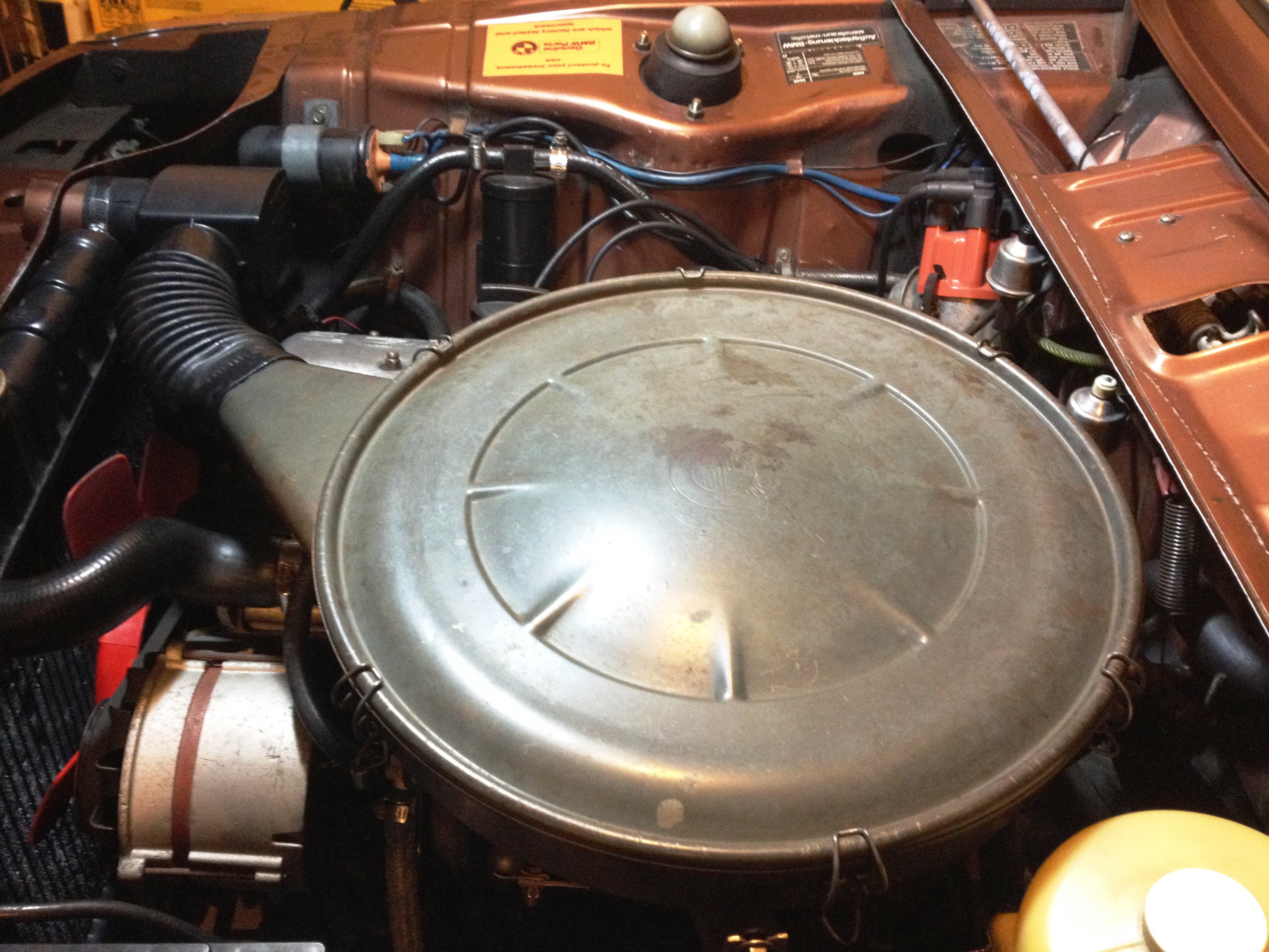 I start by saying always liked "stock look” under the hood and never cared for appearance of Weber 32/36 air filter on my 76 ’02. On the technical side, Weber set up is such that air drawn into intake manifold is always warm/hot (from engine compartment surroundings). So it is opposite of air induction system was originally designed for base model. On original setup for most parts selection of warm and/ or cold air determined by air regulator housing. The original system always let outside ambient temperature air to intake, which it is believed to make engine run smoother and better fuel efficient. Stock air cleaner and weber carburetor Integration has been discussed on this forum previously and there are lots of good information how to do this, but did not find much information on purpose of air regulator box, heat shield over exhaust manifold. So I had to learn about each component as I was acquiring them and at the end found system design quit simple and efficient. So it was learning experience and then I thought why not write article about it. Procedure is written for a 1976 model year car, which I think will be very similar for earlier model years as well, but don’t know that for sure. As I mentioned before I did not have any of original components so I had to place add on this forum under “Part Wanted” section and thanks to members that helped for me to acquire needed parts. After several search and reading up on this topic it appeared that there are at least two methods to accomplish this job if not more; one is to use an adaptor between air filter housing and carburetor; Second option is to not use an adaptor. I don’t know pros and cons of one system to another, but as I recall If none adapter version is decided then a fabricated closed-cell foam gasket should be installed between air cleaner and carburetor. Below pictures (not mine) for none adaptor version for reference. In my case I opted to go with an adaptor version. Here are photos of components that were needed; JAM air cleaner adapter Picture (13/36) Picture (13/39) Fabrication and Installation: Turn-over air filter housing, remove rubber seal and slide the adapter over the air cleaner flange Trace JAM adapter inside and three mounting holes onto air cleaner Remove adapter then remove excess material by various tools (i.e. tinsnip pliers, dremel tool) Drill previously marked holes with ¼” drill bit May want to prime/ paint modified area to prevent future rust Disconnect cable from battery negative post as a precaution Remove Weber air filter assembly including filter base plate, four screws and breather hose Fasten two brackets to intake manifold (picture 13/39, item #1 & 8) Slide down new gasket ontop of carburator Set JAM adapter over carburetor and then place gasket on top the adapter With air cleaner over JAM adapter line up 3 mounting holes. Loosely fasten air cleaner and JAM adapter to carburetor by using M6x45 screws and flat washers supplied in JAM adapter kit. Do not tighten screw yet. Fasten air cleaner to the brackets that were previously fasten to intake manifold. Purpose of these struts are to partially support weight of air cleaner and not all air cleaner weight on carburetor alone Using piece of none braided hose connect cylinder head valve cover vent opening to air cleaner tube opening Remove air regulator box cover screw and withdraw the cover. Oil the valve pivot points and check adjustment. Replace cover and screw then install the box onto snorkel (right rear of the radiator) use rubber boot to connect air cleaner to air regulator box Set new filter in and put the cover on and close clamps Slide heat shield cover over exhaust manifold and fasten it with two M6x16 bolts along with flat and wave washers. May want to apply anti-seized compound to the bolts for ease of removal just in case later on Connect heat shield to air regulator box. Curved tube (picture 13/36, item#6) Slowly try to close hood and absorb to see if hood inside makes contact with top of air cleaner housing. I did not have any interference issue, but if it seems to be the case, you may want to consider followings for remedy; Have machine shop to shorten JAM adapter height by not more than 2mm Thickness of isolation gasket sandwiched between carburetor bottom and intake manifold opening Foam pad inside bonnet Raising bonnet slightly [*]Re-connect cable to battery negative post [*]Have someone to assist with starting the car and ensure hood and air cleaner top not making contact as revving up engine, which in this case engine wants to tilt to right hand side [*]Last but not least need to paint air cleaner so it “looks stock” but have to wait till weather warms up around here. Air Regulator Housing Adjustment With the valve lever in “Summer Position” (vertical) air is drawn only from outside the car Release lever from “summer position” for other seasons. With the valve lever in the horizontal position, air drawn in from front of the car is mixed with air heated by exhaust manifold in specific proportions by the action of bi-metallic element which is dependent upon the current engine and ambient temperatures. 1/27/2014_Rev 11 point
 -
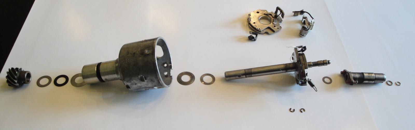 Background: I have known of my bouncing timing mark for sometimes and have learned one of the root causes is ignition distributor shaft axial and/or rotational play. So I called well known distributor rebuilder and told me rebuild time is approximately 5 weeks including shipping both ways. I would have sent it to him if it was Winter season here in Ohio, but to do it now means I won’t be driving my "Ultimate Driving Machine" for 5 weeks. So I decided to take on the task and repair it myself. I knew the distributor shaft has 0.040”axial play. The distributor is original to my 1976 BMW 2002 and part numbers stamped on distributor housing are: 0 213 170 164 // JFU 4 So, proceeded with setting engine at TDC (distributor cam aligned to distributor notch) then removed the distributor. Here are steps for disassembly: Remove contact breaker, capacitor, vacuum regulator and tabs holds distributor cap Next, note indents on distributor body where contact breaker resting on (3 places) From vacuum regulator opening, insert screw driver and pry contact breaker plate up at each indent locations. Other option for plate removal per FAQ member ('76Mintgrun'02) feedback is "rotate the plate counter clockwise to release it from the indents in the housing." Disengage two springs from cam base posts and rotate springs outward. Force cam upward with two screwdriver until retaining clip is out of groove (do not remove felt inside cam hole before cam disengagement) Move the cam upward. There was one trust washer under cam. Note a washer and O-ring clip under felt pad Clamp up helical gear wheel in a vise (use piece of leather to protect gear surface) and drill out pin with 3mm drill. Remove helical gear, trust washer(S) and fiber washer (make note of trust washers stack up) Pull out shaft with counter weights assembly. Again make note of trust washer(s) and fiber washer located underneath shaft counter weight plate. On mine fiber washer was absent under main plate, which explained excess axial play. Clean all the parts with your favorite cleaner. Remember to take a lot of pictures at each dis-assembly stages. Measure trust washer(s) and fiber washer for each group and make notes. Replacement parts: 12111350261, 07119943082, 12111351440, 12118630239 & 12118630245 (not all parts are shown) For assembly I used following instructions: Remember, axial play should be less than 0.005” post assembly completion . Use engine oil and Bosch distributor lube grease for assembly. Soak lubricating felt in engine oil, roll it and slid it inside housing. (on mine felt pad was also missing) Lubricate shaft assembly, counter weights, springs. Slide trust washer(s) and fiber ring over the shaft (rest against bottom of counter weight plate) slide shaft assembly onto the housing and push it down all the way. Slide cam trust washer and then cam over the shaft. Secure the cam with washer and ring. replace felt pad and add couple drops of engine oil on top od felt pad. Slide over fiber washer(1st) and then rust washer(s) to bottom of the shaft. Secure helical gear onto the shaft and push new pin halfway in. Check axial play with shim set. Hold distributor body firm in one hand and pull down on helical gear with other hand. Should not be able to slide in more than 0.005" shim stock over fiber washer. Once clearance is confirmed, press cone grooved pin all the way in. Lubricate contact breaker plates (bottom plate top surface and top plate bottom) with Bosch grease. Secure small "U" clip with ball bearing to contact breaker plate, then set it inside housing. Make sure its mounting holes are lined up with housing clearance holes. Install capacitor, vacuum regulator and tabs holds distributor cap. Set contact breaker to specs. Add cam grease to cam lobe , install distributor accordingly, secure distributor cap. Turn engine on and follow procedure for setting engine timing.1 point

