
Leaderboard


Popular Content
Showing content with the highest reputation since 04/14/2024 in Articles
-
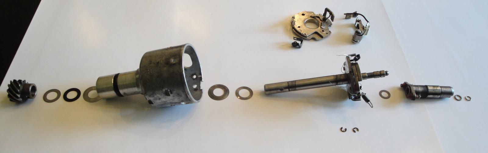 Background: I have known of my bouncing timing mark for sometimes and have learned one of the root causes is ignition distributor shaft axial and/or rotational play. So I called well known distributor rebuilder and told me rebuild time is approximately 5 weeks including shipping both ways. I would have sent it to him if it was Winter season here in Ohio, but to do it now means I won’t be driving my "Ultimate Driving Machine" for 5 weeks. So I decided to take on the task and repair it myself. I knew the distributor shaft has 0.040”axial play. The distributor is original to my 1976 BMW 2002 and part numbers stamped on distributor housing are: 0 213 170 164 // JFU 4 So, proceeded with setting engine at TDC (distributor cam aligned to distributor notch) then removed the distributor. Here are steps for disassembly: Remove contact breaker, capacitor, vacuum regulator and tabs holds distributor cap Next, note indents on distributor body where contact breaker resting on (3 places) From vacuum regulator opening, insert screw driver and pry contact breaker plate up at each indent locations. Other option for plate removal per FAQ member ('76Mintgrun'02) feedback is "rotate the plate counter clockwise to release it from the indents in the housing." Disengage two springs from cam base posts and rotate springs outward. Force cam upward with two screwdriver until retaining clip is out of groove (do not remove felt inside cam hole before cam disengagement) Move the cam upward. There was one trust washer under cam. Note a washer and O-ring clip under felt pad Clamp up helical gear wheel in a vise (use piece of leather to protect gear surface) and drill out pin with 3mm drill. Remove helical gear, trust washer(S) and fiber washer (make note of trust washers stack up) Pull out shaft with counter weights assembly. Again make note of trust washer(s) and fiber washer located underneath shaft counter weight plate. On mine fiber washer was absent under main plate, which explained excess axial play. Clean all the parts with your favorite cleaner. Remember to take a lot of pictures at each dis-assembly stages. Measure trust washer(s) and fiber washer for each group and make notes. Replacement parts: 12111350261, 07119943082, 12111351440, 12118630239 & 12118630245 (not all parts are shown) For assembly I used following instructions: Remember, axial play should be less than 0.005” post assembly completion . Use engine oil and Bosch distributor lube grease for assembly. Soak lubricating felt in engine oil, roll it and slid it inside housing. (on mine felt pad was also missing) Lubricate shaft assembly, counter weights, springs. Slide trust washer(s) and fiber ring over the shaft (rest against bottom of counter weight plate) slide shaft assembly onto the housing and push it down all the way. Slide cam trust washer and then cam over the shaft. Secure the cam with washer and ring. replace felt pad and add couple drops of engine oil on top od felt pad. Slide over fiber washer(1st) and then rust washer(s) to bottom of the shaft. Secure helical gear onto the shaft and push new pin halfway in. Check axial play with shim set. Hold distributor body firm in one hand and pull down on helical gear with other hand. Should not be able to slide in more than 0.005" shim stock over fiber washer. Once clearance is confirmed, press cone grooved pin all the way in. Lubricate contact breaker plates (bottom plate top surface and top plate bottom) with Bosch grease. Secure small "U" clip with ball bearing to contact breaker plate, then set it inside housing. Make sure its mounting holes are lined up with housing clearance holes. Install capacitor, vacuum regulator and tabs holds distributor cap. Set contact breaker to specs. Add cam grease to cam lobe , install distributor accordingly, secure distributor cap. Turn engine on and follow procedure for setting engine timing.2 points
 -
 Installation of BMW 2002 Door Glass and Door Components Larry Gray @2002#3 and Karl Bergmann @bergie33 (6/27/23) A door or window component installed out of order can easily block the installation of a subsequent part(s). The result can be wasted time, lost energy, and mental, physical, emotional, and spiritual upheaval. Therefore, a reasonable and practical order of installation of components is important to overall '02 happiness. This tech article will cover the proper order of installation of the door internal components, the specific parts that are installed in the doors, and the necessary hardware for a complete installation. General Order of Operation 1. grommets 2. connecting rod 3. door opening/lock mechanism, inner door handle mechanism, & connecting rod 4. window glass, rubber seal, & window guide rail 5. window regulator & window regulator arm 6. vent window regulator 7. vent window frame, front vent window frame bracket, front upper door bracket & front lower door bracket 8. male tab & female tabs 9. rear window guide rail 10. window guide rail, window regulator arm & guide slot 11. front window bracket , green plastic insert, & front upper stopper 12. front window bracket 13. rear window holder, rear upper stopper, distance rubber, nylon bushings 14. adjustments General Installation Let's assume (i) everything [except the door stop mechanism] has been removed from the door (cards, glass, door mechanisms, locks, handles, fasteners, etc., (ii) each piece has been meticulously cleaned, rehabbed, replaced, and well lubricated, (iii) all necessary rust, filling, and painting issues have been resolved, and (iv) all parts are ready to be installed. Notes · The guidelines in this article refer to 2002's in general. Individual cars and models might vary. · Take photos of all components, fasteners, nuts, bolts, etc. in their pre-removal position. · Use a scribe to outline the pre-removal position of each bolt head, washer, and fastener. · Keep all bolts and fasteners slightly loose during installation to facilitate adjustments · Keep adjusting the forward window bracket (L-shaped; 2 wheels) throughout the process so both wheels continually touch the vent window frame regardless of the position of the window (up or down) - one wheel touching the front and one wheel touching the back of vent window frame. · Make sure each original hole drilled through the window glass contains a small plastic bushings/sleeve through which bolts will pass. These bushings/sleeves are easily lost because they are small and hidden under rubber buffers which attach to the glass. · Keep like-function bolts fasteners together, especially short bolts. 1. Install 2 new clear plastic grommets into the door opening/lock mechanism and 1 grommet into the inner door handle mechanism. This will fix annoying door rattles when driving and when closing the doors. 2. SEE END NOTE. Install one end of the long connecting rod into the door opening/locking mechanism and the other end of the rod into the inner door handle mechanism. 3. SEE END NOTE. Install the door opening/locking mechanism, the inner door handle mechanism, and the connecting rod at the same time. Test for proper opening, closing, and locking functions. 4. Place window glass (with likely-attached rubber seal and window guide rail) into the door and let it rest onto the bottom of the door. Yes, all by its lonesome. This is the only time when insertion of the glass will be easy. You will be working around the glass, which will be secured later. 5. Install the window regulator (3 short bolts). Lower the regulator arm almost to its lowest point. 6. Install the vent window regulator. 7. Install the vent window frame (5 bolts). Attach the front vent window frame bracket to the front upper door bracket (near the top door hinge), the frame to the door just below the vent window, the lower frame to the front lower door bracket, and that bracket to a shelf in the bottom of the door. 8. Connect the vent window frame male tab and the vent window regulator female tab (1 bolt). Test for proper function. 9. Install the rear window guide rail (4 bolts). 10. Insert the end of the regulator arm into the guide slot in the window guide rail. The small washer should end up on the outside of the rail and the large washer should end up on the inside of the rail. 11. Install the front window bracket (L-shaped, 2 wheels) and the front upper stopper (same bolts). Make sure one wheel rides on the front of the vent window frame and one rides on the back of the frame. If you manipulate it properly, it will snap into place. Yes, it will. The green/white plastic insert must be forced into the rail. 12. Push the glass securely into the vent window frame felt channel, manipulate the front window bracket so both wheels touch the rail, and tighten the bracket bolts. This bracket is the main support and guide for the window. 13. Attach the rear window holder (has two white plastic inserts) onto the rear window guide rail. The rear window holder, the rear upper stopper, the plate, and the distance rubber might already be attached to the window glass. When assembling the rear window holder, the distance rubber folds over the bottom of the window. From outside to inside, the order is hex bolts, washers, rear stopper, rear window bracket, rubber buffer, glass, nylon bushings (in the holes; DO NOT lose them!), rubber buffer, plate. The rear window guide rail is the major part involved in adjustment and smooth operation. You might be moving it more than any part during adjustment. 14. Readjust the front window bracket to make sure both of its wheels touch the vent window frame rail. END NOTE: Steps 2 and 3 can be the last steps in the installation if desired. Such action will provide valuable room for Steps 4 through 13. However, completing Steps 2 and 3 at the end will involve some unanticipated planning, finagling, twisting, and thought processes. It will be a puzzle and you will find its solution really quite easy...but only in hindsight. Everything is likely in its proper place, and you are almost done. Now, the window must be adjusted - not much if you are lucky. Our FAQ2002 site has several posts which provide excellent guidelines for adjustments: freedom and ease of movement, maximum height (determined by the adjustable 2 stops; one on each end for the bottom of the window glass), lean out/in, evenness of raising and lowering (top edge raises and lowers parallel to the top edge of the door), snugness of the edges of the window and vent window frame against weather stripping around the door opening (to keep out water), snugness of the glass against the outer squeegee, etc. Details of the Installation, Assembly, Hardware, and Fasteners Here are the different assembly processes · Parts and Hardware/Fasteners · Vent Window Frame · Window Regulator · Rear Window Guide · Door Opening/Locking Mechanism & Inner Door Handle Mechanism These are arranged below to show the parts, hardware, and assembly for each section and to provide additional details to the above assembly instructions. A. Parts and Hardware/Fasteners 1. The Door 2. The Parts 3. Hardware and Fasteners (# needed for both doors) · M6x16 bolts with 2 captured washers (20) · M6x18 bolts (4) · M6x16 bolts (4) · M6x8 bolts (6) · M6x16 flat head Philips screw (2) · M6 toothed washers (14) · M6 flat washers large diameter (16) · M6 flat washers small diameter (2) · M6 hex nuts (2) · M6x12 Oval head phillips screws (4) · M6x16 Flat head screws (4) · M5x10 hex bolts (4) · M5 Toothed washers (4) B. Vent Window Frame 1. Vent Window Frame to door (2 holes below vent window) · M6x18 bolts (4) · M6 toothed washers (4) · M6 flat washers large diameter (4) 2. Front Vent Window Frame Bracket to Front Door Bracket (Upper door bracket is attached to the door at the upper door hinge with 2 M6x16 bolts with 2 captured washers). · M6x16 bolts with captured washers (4) 3. Vent Window Frame to Front Lower Door Bracket · M6x16 flat head Philips screw (2) · M6 toothed washer (2) · M6 flat washer small diameter (2) · M6 Hex nuts (2) 4. Front Lower Bracket to lower door (Bracket is attached to the door at the lower raised platform.) · M6x16 bolts with 2 captured washers (4) 5. Vent Window Regulator to vent window and door · M6x16 bolts (2) – to attach vent window frame male tab and the vent window regulator female arm · M6x16 bolts with 2 captured washers (4) – to attach the vent window regulator to the door. C. Window Regulator Regulator Arm Guide Slot 1. Window Regulator to door · M6x8 hex bolts (6) · M6 toothed washers (6) · M6 large diameter flat washers (6) 2. Window Guide Rail and Rubber Seal to window · split pin 4mmx28mm (or 5/32” x 1-1/2” ) (2) · nylon bushing - 1/4" od x 1/4" long, for #8 screw (2) 3. Front Window Bracket to Window Guide Rail and Front Upper Stopper (Front upper stopper is attached on the opposite side of the guide rail from the roller bracket, using the same attaching bolt) · M6x16 bolt with 2 captured washers (4) D. Rear Window Guide 1. Rear Window Holder, Distance Rubber, Rear Upper Stopper, and Plate to window · M6x25 hex bolts (4) · M6 flat washers, large diameter (4) · Nylon Bushings – 10mm od x 6mm id x 5mm thick (4) 2. Rear Window Guide Rail to upper door · M6x16 hex bolts (2) · M6 Toothed washers (2) · M6 flat washers, large diameter (2) 3. Rear Window Guide Rail to lower door · M6x16 bolts with 2 captured washers (4) E. Door Opening/Locking Mechanism & Inner Door Handle Mechanism 1. Door Opening/Locking Mechanism to Door · M6x12 Oval head Philips screws (4) 2. Door Latch Bump Stop to Door Opening/Locking Mechanism · M6x16 Flat head screws (4) 3. Inner Door Handle Mechanism to Door · M5x10 hex bolts (4) · M5 Toothed washers (4) · M5 flat washers, large diameter (4)1 point
 -
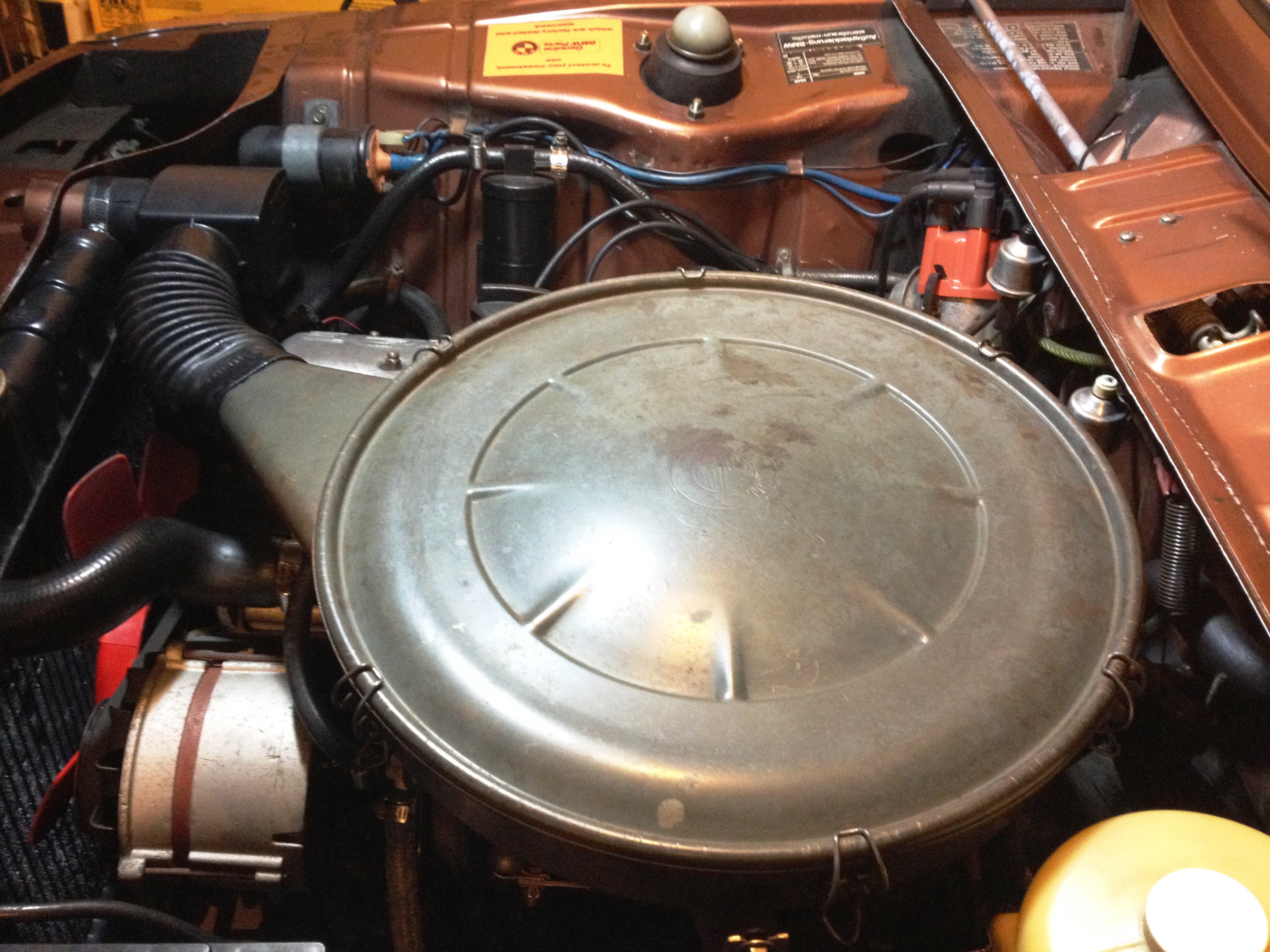 I start by saying always liked "stock look” under the hood and never cared for appearance of Weber 32/36 air filter on my 76 ’02. On the technical side, Weber set up is such that air drawn into intake manifold is always warm/hot (from engine compartment surroundings). So it is opposite of air induction system was originally designed for base model. On original setup for most parts selection of warm and/ or cold air determined by air regulator housing. The original system always let outside ambient temperature air to intake, which it is believed to make engine run smoother and better fuel efficient. Stock air cleaner and weber carburetor Integration has been discussed on this forum previously and there are lots of good information how to do this, but did not find much information on purpose of air regulator box, heat shield over exhaust manifold. So I had to learn about each component as I was acquiring them and at the end found system design quit simple and efficient. So it was learning experience and then I thought why not write article about it. Procedure is written for a 1976 model year car, which I think will be very similar for earlier model years as well, but don’t know that for sure. As I mentioned before I did not have any of original components so I had to place add on this forum under “Part Wanted” section and thanks to members that helped for me to acquire needed parts. After several search and reading up on this topic it appeared that there are at least two methods to accomplish this job if not more; one is to use an adaptor between air filter housing and carburetor; Second option is to not use an adaptor. I don’t know pros and cons of one system to another, but as I recall If none adapter version is decided then a fabricated closed-cell foam gasket should be installed between air cleaner and carburetor. Below pictures (not mine) for none adaptor version for reference. In my case I opted to go with an adaptor version. Here are photos of components that were needed; JAM air cleaner adapter Picture (13/36) Picture (13/39) Fabrication and Installation: Turn-over air filter housing, remove rubber seal and slide the adapter over the air cleaner flange Trace JAM adapter inside and three mounting holes onto air cleaner Remove adapter then remove excess material by various tools (i.e. tinsnip pliers, dremel tool) Drill previously marked holes with ¼” drill bit May want to prime/ paint modified area to prevent future rust Disconnect cable from battery negative post as a precaution Remove Weber air filter assembly including filter base plate, four screws and breather hose Fasten two brackets to intake manifold (picture 13/39, item #1 & 8) Slide down new gasket ontop of carburator Set JAM adapter over carburetor and then place gasket on top the adapter With air cleaner over JAM adapter line up 3 mounting holes. Loosely fasten air cleaner and JAM adapter to carburetor by using M6x45 screws and flat washers supplied in JAM adapter kit. Do not tighten screw yet. Fasten air cleaner to the brackets that were previously fasten to intake manifold. Purpose of these struts are to partially support weight of air cleaner and not all air cleaner weight on carburetor alone Using piece of none braided hose connect cylinder head valve cover vent opening to air cleaner tube opening Remove air regulator box cover screw and withdraw the cover. Oil the valve pivot points and check adjustment. Replace cover and screw then install the box onto snorkel (right rear of the radiator) use rubber boot to connect air cleaner to air regulator box Set new filter in and put the cover on and close clamps Slide heat shield cover over exhaust manifold and fasten it with two M6x16 bolts along with flat and wave washers. May want to apply anti-seized compound to the bolts for ease of removal just in case later on Connect heat shield to air regulator box. Curved tube (picture 13/36, item#6) Slowly try to close hood and absorb to see if hood inside makes contact with top of air cleaner housing. I did not have any interference issue, but if it seems to be the case, you may want to consider followings for remedy; Have machine shop to shorten JAM adapter height by not more than 2mm Thickness of isolation gasket sandwiched between carburetor bottom and intake manifold opening Foam pad inside bonnet Raising bonnet slightly [*]Re-connect cable to battery negative post [*]Have someone to assist with starting the car and ensure hood and air cleaner top not making contact as revving up engine, which in this case engine wants to tilt to right hand side [*]Last but not least need to paint air cleaner so it “looks stock” but have to wait till weather warms up around here. Air Regulator Housing Adjustment With the valve lever in “Summer Position” (vertical) air is drawn only from outside the car Release lever from “summer position” for other seasons. With the valve lever in the horizontal position, air drawn in from front of the car is mixed with air heated by exhaust manifold in specific proportions by the action of bi-metallic element which is dependent upon the current engine and ambient temperatures. 1/27/2014_Rev 11 point
 -
 If you own a BMW 2002 and want to keep it running smoothly, you need a reliable repair manual. Our online BMW 2002 repair manual is the perfect resource for all your repair and maintenance needs. This comprehensive manual contains step-by-step instructions, detailed diagrams, and helpful tips to help you troubleshoot and repair any issues that arise. Whether you're a professional mechanic or a DIY enthusiast, our BMW 2002 repair manual has everything you need to maintain and repair your vehicle. From routine maintenance tasks to more complex repairs, our manual provides clear and concise guidance to help you get the job done right. Our online BMW 2002 repair manual is available for instant access, so you can get started on your repairs right away. With our user-friendly platform, you can quickly and easily find the information you need, making it the perfect resource for any BMW 2002 owner. The relevant specifications are always provided at the beginning of each main group. Introduction Axle - Front Axle - Rear Automatic Transmission Body Equipment Body Work Brakes Clutch Electrical System - General Engine - Electrical Engine and Mechanical Equipment (Miscellaneous) Exhaust Foot Pedals Fuel System Fuel Tank Gear Selection Gearbox Drive Shaft Heat and Air Conditioning Instrument Panel Radiator Radio and Antenna Seats Steering Whee Alignment Wheels and Tires Wiring Diagrams Wiring Diagram (Oversized)1 point
 -
 Written by Richard Stern Saturday, 17 September 2005 Adjusting the Window regulator Adjusting the Window regulator By Richard Stern If your front side windows don’t shut fully there may be a cheap easy answer before buying a second-hand window regulator as new ones are NLA Tools required: Large flat blade & Phillips screwdrivers Block of wood 10mm socket or spanner Old wire coat hanger Some spare plastic door panel clips Instructions: With the wire coat hanger, poke out the disc from the quarter light knob, by poking it through the hole at the back of the knob & push out the blanking disc way from the door, this will expose the screw holding the knob on – Remove. Remove all screws holding the door handle rest, carefully pry off the top chrome surround to expose top screw. Plastic insert on door handle also pushes off away from the center. With all handles and winders removed, carefully pull lower part of door panel away from door, there are plastic clips that will properly break, but they are cheap & easy to replace. Keep going all around the door working to the top until all clips are dismantled. Door panel should now lift upwards; it might need some wriggling. Loosen the 3x 10mm bolts holding the window winder to the regulator. Temporarily put the window winder handle on, & wind the window fully up. Either pull window up with your hands to gain another 5mm or so. Or use a block of wood & place it in the bottom of the door. Wind the window down onto the wooden block & then give it an extra quarter of a turn. Tighten the x3 10mm screws. The window should now wind up fully. Refit is reverse of the removal process, replacing any broken clips where necessary. Please post any questions or comments to the Message Board!1 point


