


rufurt
-
Posts
61 -
Joined
-
Last visited
-
Feedback
0%
Content Type
Profiles
Articles
BMW 2002 and BMW Neue Klasse Wheels
Colors
Steering Wheels
Production Years
Models
Registry
BMW 2002 Vendors and Shops
BMW 2002 Books
The Hack Mechanic
Forums
Blogs
Gallery
Events
Store
Books
Community Map
Videos Directory
Posts posted by rufurt
-
-
AustrianVespaGuy, I read your write up of rerouting the power away from the switches. It makes sense and is simple. Why in the hell didn't they do that from the factory? Was it the cost of an extra relay that they balked at?
I think I can afford a relay and a length of red wire. Next time I am at out I'll pick them up.
John, great diagram! Puts mine to shame. So mush easier to read than the factory black and white with miniscule micro-font.
-
Well I spent the weekend learning about the Hi and Low beam wiring and relays. It started with the turn signal/Hi and low beam switch not being able to switch to Hi beams. I could flash Hi beams by pulling the stalk towards me, but pushing it to the constant on position did nothing.
Luckily I had a spare switch/stalk from a wiring harness I purchased years ago. I tested the spare in-situ and it worked. Swapped it out. I believe the turn signal stalk is the same for late models 74-76 left side of steering column.
Then I went about trying to figure out what went wrong with the original switch. To take it apart I had to drill out the hollow rivets that held it together. Once opened I could see the contacts for the turn signal and the Hi/Low beam. Ignoring the turn signal contacts the high and low beam assembly has three contacts:
A: Connected to the Yellow wire from the Light switch on the dash. When pulled all the way out to the ON position the Light switch connects the yellow wire to the green wire powered through the ignition switch.
B: Connected to the White wire via a springed contact arm. It has three position: touching nothing, touching A, or touching C
C; Connected to the Green wire coming from Ignition switch. Always has power when Ignition switch is in the running position.
There is also an Arm (D) that can be moved by pulling or pushing the stalk into one of three positions: pulling towards driver momentarily = Flash Hi Beams, middle = Low Beam, pushed away from driver = Hi Beams on.
When the Ignition switch is in the running position and the Turn signal/Hi-Low beam stalk is in the Low Beam position, the Low Beam relay gets power from a Green wire from the Ignition switch and (I think) grounds through the Hi Beam bulbs filament via the Purple/White wire. This energizes the relay and closes the contacts and connecting the Yellow/White wire to the Yellow wire which goes to fuses 9 and 10 to power the Low Beams. In the diagram the B contact arm is not touching anything as the D holds B between A and C. Basically the Low Beam relay stays constantly energized when the stalk is in the Low Beam position, even when the lights are off.
When you pull the stalk towards you it pushes D to push B into contact with C momentarily thus flashing the Hi Beams by sending power to the HI Beam relay which energizes and closes its contacts connecting the powered Green Ignition wire to the White wire that goes to fuse 11 which goes to the headlights via Purple/White.
What stumped me was that the Purple/White wires, ( besides going to the left and right headlight Hi Beam filaments and to the Hi Beam indicator on the dash) goes to the Low Beam relay coil! The same Purple/White wire that grounded the Low Beam relay coil via the Hi Beam filaments. My guess is that the coil in the Low Beam relay has enough resistance that being energized (while Low Beams are on) doesn't provide enough power to turn on the Hi Beam filaments.
When you push the Turn signal/Hi-Low beam stalk away from you D relaxes and stops pushing B. This allows B to spring up and contact A. This allows power from the Yellow wire to flow through the Blue/White wire to energize the High Beam relay.
Whenever the Hi Beam relay is energized the power from the Green wire stops flowing through the Low Beam relay's coil and goes instead through the Hi Beam filaments. This turns of the Low Beam relay and shuts off the Low Beam filaments.
Hope this helps, and sorry about the hand drawn diagrams being a little sloppy.

-
 3
3
-
-
Here is a link to a printable backer paper for the fuse box. Made it for my 1976 because the original was so dirty you couldn't make out the colors. 1976 had a few changes from the 1973 fusebox.
-
1
-
-
hi Matt,
Do you have a right rear window latch?
-
An old Polaroid from 1998 after a trip to the beach with my buddy. I'd had the car about a year. I'm on the right.
A few years later in 2000
Now
If you notice, I never had the rocker trim on 20 years ago and I still haven't figured out how to get it to attach.
-
2
-
-
Heh, that's definitely one way to solve it.
-
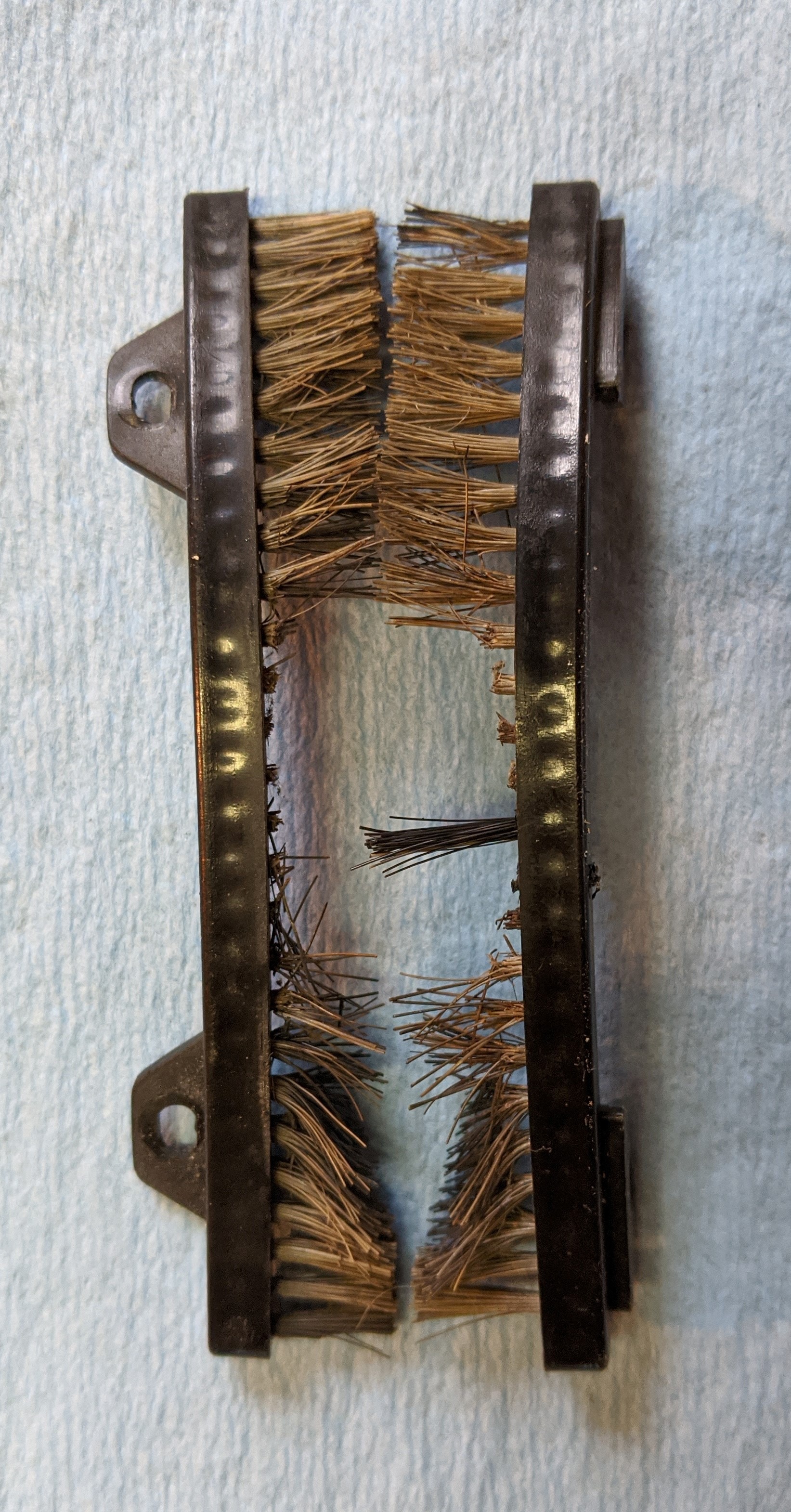
Put new brushes in my automatics shift cover. Even wrote a FAQ for it.
-
4
-
-
Thanks John.
Excellent photo. That helps.
-
The brushed in my automatic (1976) shift cover had become brittle with age and almost half had broken off, leaving it looking very poor.
You can't buy the original parts anymore. So I though I'd make my own.
It took a while to find something similar enough to look right, cheap, and the right size. Took a while but I got 2 out of the 3. They size isn't exactly right, but we'll fix that.
I ordered a strip brush from McMaster-Carr https://www.mcmaster.com/74405t1
You can buy it by the foot, which is nice, as I didn't want to buy in bulk.
The bristles are 0.006" in diameter, the bristles in the original varied from 0.006"-0.009".
The width from back of base to end of bristle is 3/4" which is longer than the original's 0.66". So you'll need to trim the bristles.
Here is pic of the brush (after i started trimming)
here is the inside of the shift cover with old brushes removed.
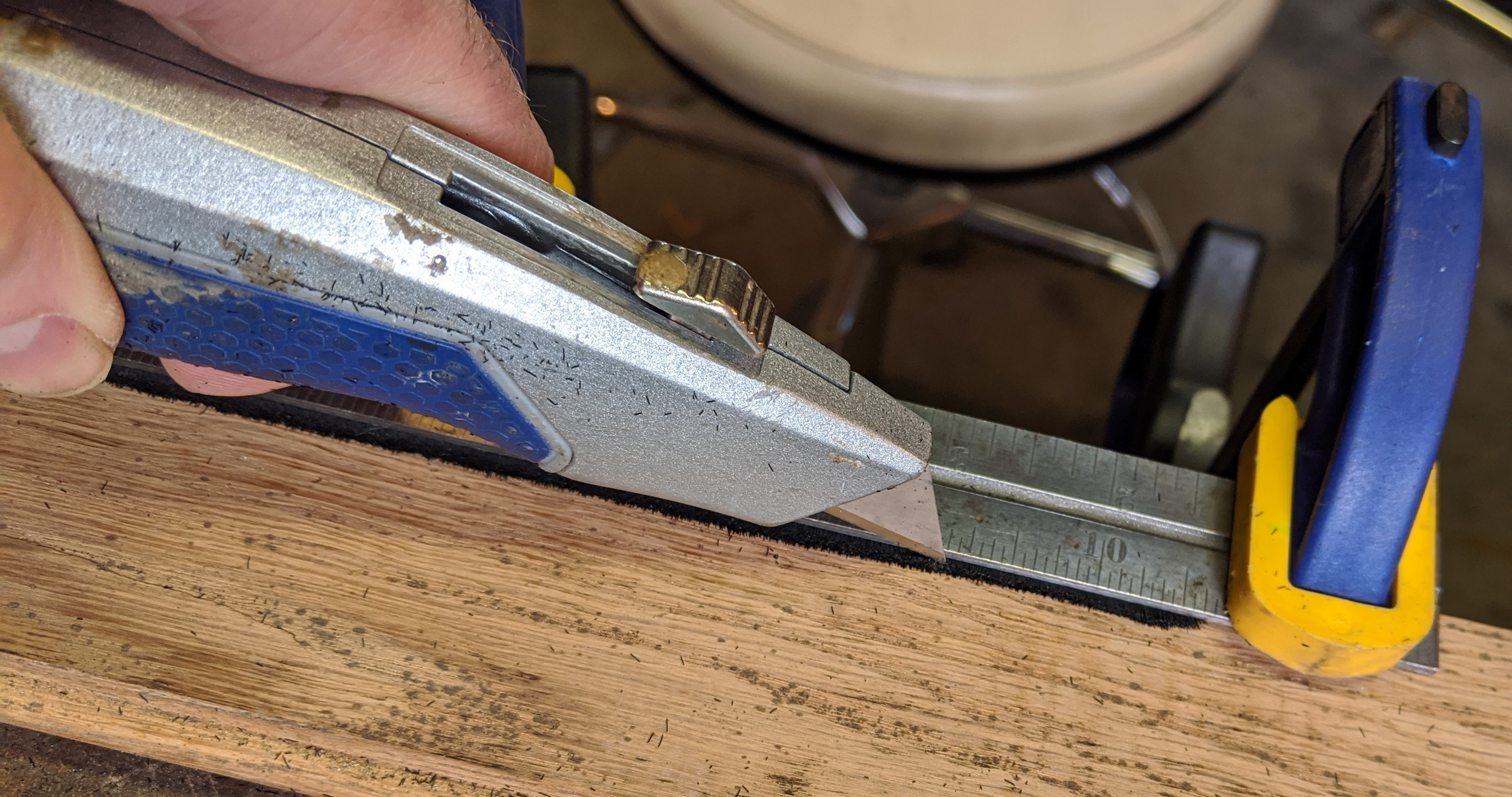
Using scissors seemed like a bad idea (unless you are a barber), so I decided to clamp the bristle in place with a straight-edge. It will hold them in place and make so you can adjust the depth of cut. My first cut was exactly the amount I need to trim to get the width down to 0.66".
Use a new razor blade so you don't have to press hard.
When I took it out to measure, I had only cut about half what I needed.
What happens is, as you drag the blade along the bristles you end up tilting them from perpendicular to the spine. They bunch up together and hide under the straight edge.
Since I didn't know exactly how much extra needs to protrude beyond the straight-edge, I had to creep up on the desired width with successive cuts.
Now you'll need to bend the strip to match the curve in the cover. A vise helps. Do a little at a time and then move the strip.
Check the bend often. The strip bends more towards the aft part of the shift cover.
Once you are satisfied with the bend. It's time to glue them in. I used a little JB-Weld Kwik (who wants to wait 4 hours for it to set)
Here is the cover with brushes installed
The only imperfection from the outside is the angle of the bristles. Bending the strip causes the bristles to fan upwards a little. They don't stay in the plane of the cover. I can live with that.
Here is how the shift lever looks in the bristles (on the bench). It moves smoothly through the bristles.
One more piece of the car looking good. Next is the shift numbers (notice the vacant slot on the left).
I have no idea why this image appears here, I can't seem to delete it. oh well. Extra image of the brush.
-
1 hour ago, John76 said:
Do you have the bracket in the right location? It is mounter close to the firewall and the panel is tucked under the hard plastic steering wheel cover. Hope my picture helps with your project.
Great pic, that helps a lot. I can see that the panel distorts some. I was leery of bending the board to much as I don't want to break it
Did the other end of that panel go over or under the column cover?
Thanks
-
I am trying to install the under dash panel the covers the steering column in my 1976 Automatic. I see the bracket attached to the steering column, and have read the panel screws into that. What I have noticed is that the holes on the panel are further apart the holes in the bracket. Only the passenger side panel hole to the bracket line up well.
I have purchased a new panel and its hole match the original, so it doesn't seem to be a mistake. I seem to lack a bit of understanding on how the holes in the panel and bracket mate.
Also, does the front of the panel go above or below the steering column cover (not the padded one). The original panel had clip on sheet metal nuts so that leads me to believe it goes above the cover and the screws go through the cover into the panel sheet metal nuts. It doesn't fit above the cover well at all. I am afraid I will break it if I force it. I have seen images of it both above and below the cover. Just wondering how it was originally. I can always transfer the clip-nuts to the cover and have the panel screw into it from below.
thanks,
-
1 hour ago, AustrianVespaGuy said:
Ok, so BIG thank you for mentioning that this is a '76, as that makes the circuit quite a bit different from the earlier models (including my '75!) Secondly, your testing method was definitely on the right track, but I think you missed one place that brown/blue wire goes, which I also think is where your issue probably lies, and that's that loathed seatbelt timer relay. BOTH that brown/blue AND green/white wires go to it, so if it were 'stuck shut' or something I think it would exhibit exactly your symptoms, including the hole 6 reading low resistance to ground. I think it's somewhere up under the dash, maybe the best way to find it would be to trace the yellow/brown wire from the 'fasten seat belt' dash pod down to it. Should have 5 wires: yellow/brown, brown/blue, brown/white, white/green, and a solid brown ground. See if you can find that bastard and if disconnecting it solves your problem!
That was it (I think) the little seat belt that relay. I disconnected it after I found it above the hood latch. The Brake light went out.
Plugged it back in to see if it would replicate the problem. About 3 seconds after I turned the key the relay clicked and the light went out. My guess is it got stuck on after when I moved it around laying carpet. In my struggle to disconnect I think I unstuck it.
I am leaving it disconnected as my car doesn't have any of the other bits that make it work anyway. It was a vestigial relay that didn't do anything.
I rechecked and am still getting about 10 Ohms from Brown/Blue to ground. Everything seems to work though.
Thanks a bunch.
-
2
-
-
Hi All,
The Brake light on the dash is on and won't go out in my 1976 Automatic. I checked the connections that are supposed to trigger it. I disconnected the brown/blue wire to handbrake switch, the brake fluid reservoir, and the brake pressure balance switch. The light stayed on even with all those wires disconnected. Since it is a 1976 the Brake light won't light up for low fuel as there isn't a connection for that. Only 2 wires to fuel tank for the gauge.
My first thought is that there is a break in the Brown/Blue wire's insulation and that is grounding itself somewhere. When I tested the Brown/Blue to ground I got continuity. I started looking through wires for a break. Haven't found one yet.
Next I took out the instrument cluster. I disconnected the large circular connector. I plugged my multi-meter into the 5 hole (Brown/Blue wire) and then to ground. No connection. That leads me to think that the Brown/Blue isn't grounding itself through a break. I checked 5 to handbrake wire end (Brown/Blue) and got continuity, just to be sure.
I then stuck the probe into the 6 hole, Green/White (this is power from the fuse 12) to ground and got the beep of continuity. What? If that already has ground why would the Brake light even be on, wouldn't it short to ground? I checked a few other holes on the circle connector and a few more seem to be grounded to the body?
I turned the ignition switch, the lights work, signals work, even the wee lights that light up the gear selector came on.
I am so confused.
Any ideas?
thanks,
-
Back in college, I had a CD of radial engine noises from aircraft. https://aircraftrecords.com/products/round-sounds-vol-2
I had that cranked up on the stereo and my buddy gets in the car. I think we were listening to the T-28 idling after engine start. My buddy says, " Man, you car sounds weird today"
Took him a while to figure it out.
-
1
-
-
I am in the same boat except I still have the plastic (faded cracked and glued back together) numbers without the top layer.
I heard that some people are taking an image of the numbers, printing them on transparency film and using them on a backer of sorts. Not a bad idea.
No one seems to have any NOS for this part. I've looked, found a site that "has" them, placed an order only to get an email the next day saying "oops that isn't in stock"
Here's the back side of mine before I glued it. On top it is just the white of the plastic.
-
I heard back from the BMW Archive group. My '02 rolled off the line May 24th, 1976 and delivered to North America on May 31st.
Kinda cool to know exactly when your car came off the line.
I think I'll save money and not buy a VIN plate. The number's still pressed into the steel on the passenger side quarter panel, though it is covered with paint.
My engine number does not match however. Oh well, I didn't really think it would.
-
1
-
-
On 3/23/2020 at 10:57 AM, adawil2002 said:
The Brushes are here, http://www.bmwmobiletradition-online.com/bmw/showparts.do?model=ST16&mospid=47140&btnr=51_3346&hg=51&fg=35
I have an automatic base but not the PROD21.
Tried ordering the brushes. It accepted payment, but the next day refunded as they are out of stock.
oh well.
-
 1
1
-
-
Sent my VIN to BMW Group Archives to see what they say.
thanks for the photo MintGrun
-
2
-
-
Right now I am undecided. Just trying to figure what it would have if it did have one. My bet is it didn't, as there aren't any rivet holes where it would go.
-
cool, thanks,
Interesting that the 75/76 VIN plates don't have kg fields filled while older plates do.
-
Hi All,
My 1976 automatic doesn't have a VIN plate. when searching the number on realoem.com it says May of 76. That might fall into the months where there were no VIN plates.
If i were to get a plate, what would the Type field say?
BMW2002
BMW2002/2002tiiUSA
or was there a separate typ for automatics? Was there a BMW2002A ?
thanks,
-
Hi IanIreland,
I am working on it now, but can always install another whenever. It's not difficult to remove. The biggest problems with mine are the letters being impossible to read in the daylight and the brushes on the side.
Could you send me a pic of the lettering for reference? I am not sure exactly how it is supposed to look in daylight. Mine is all white on top.
thanks,
-Quinn
-
Thanks, for the link.
-
Do you still have the driver's window regulator? How is the crank bushing? That is what went bad on mine, when I try to crank the handle it wobbles badly and disengages the gears.
Cheers


Hi and Low beam wiring on a 1976
in BMW 2002 and other '02
Posted
I was thinking of going with the Koito H4 headlamps from danielsternlighting.com
They have a replaceable bulb which is nice. Much more convenient to change a bulb than an entire sealed bulb/unit that came with the car.
Bought some relays to install and some red wire. Once the relays arrive I will install them to protect the switches.
With all this electrical work I have really come to appreciate the color wire diagram I have. So much easier to read.